02: Basic tools, procedures, and electronics
Assignment
- Cut pieces from two different materials and join them. Document this.
- Add a fabricated component to a circuit, so that it does something (motion or light).
- Use a multimeter to measure the behavior of your circuit. Document your work and learning.
- Sign up for a free student Fusion 360 account with Autodesk
Tool Usage
Today I learned the proper way to use several tools in the shop, including:
- Hacksaws vs traditional saws. We also used a Japanese variant
- Razor blades used to cut cardboard
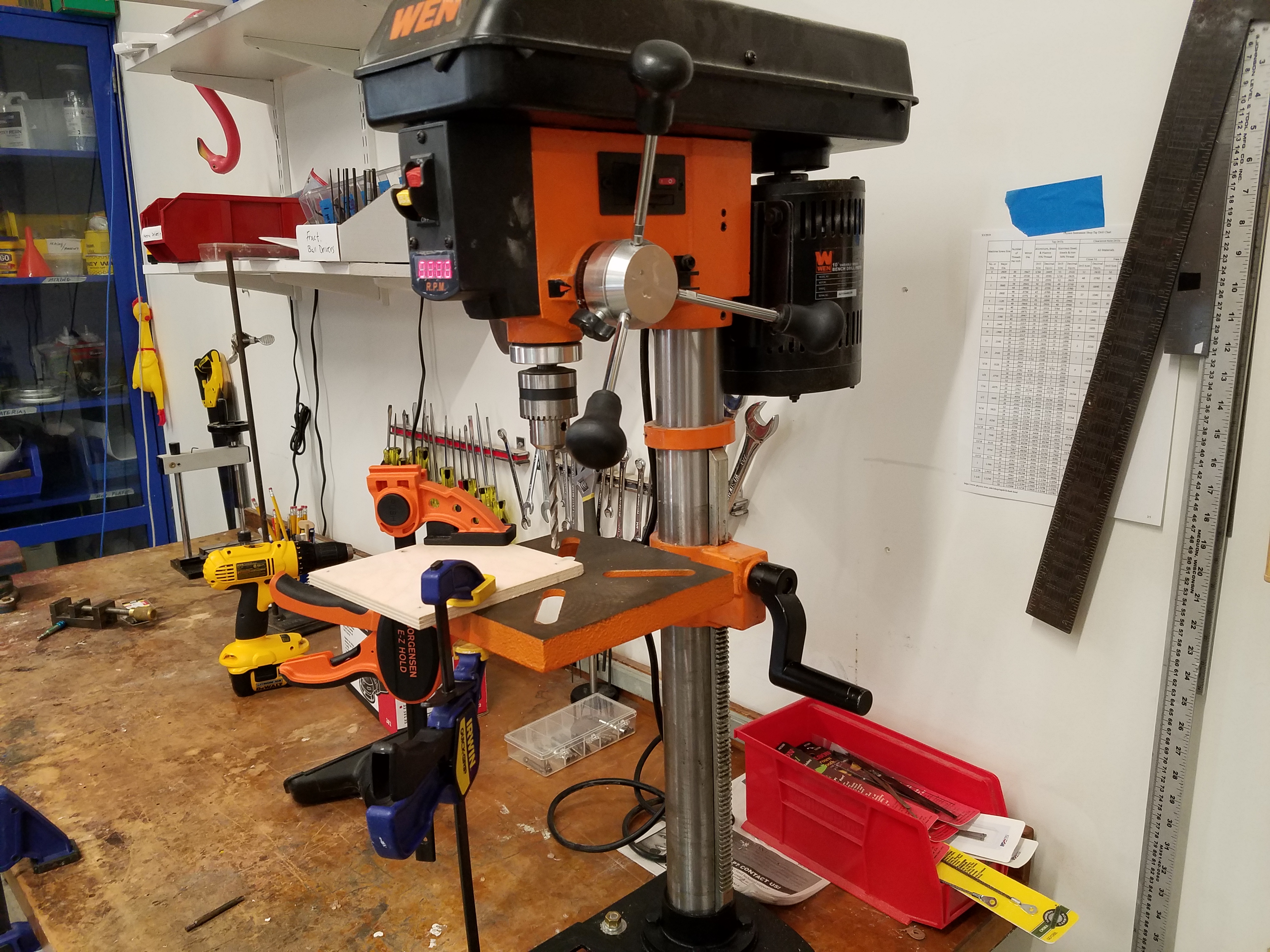
- Drill Press
- Measuring tools (for determining precision points for drilling)
- Filer
- Epoxy and other glues
- Heat gun
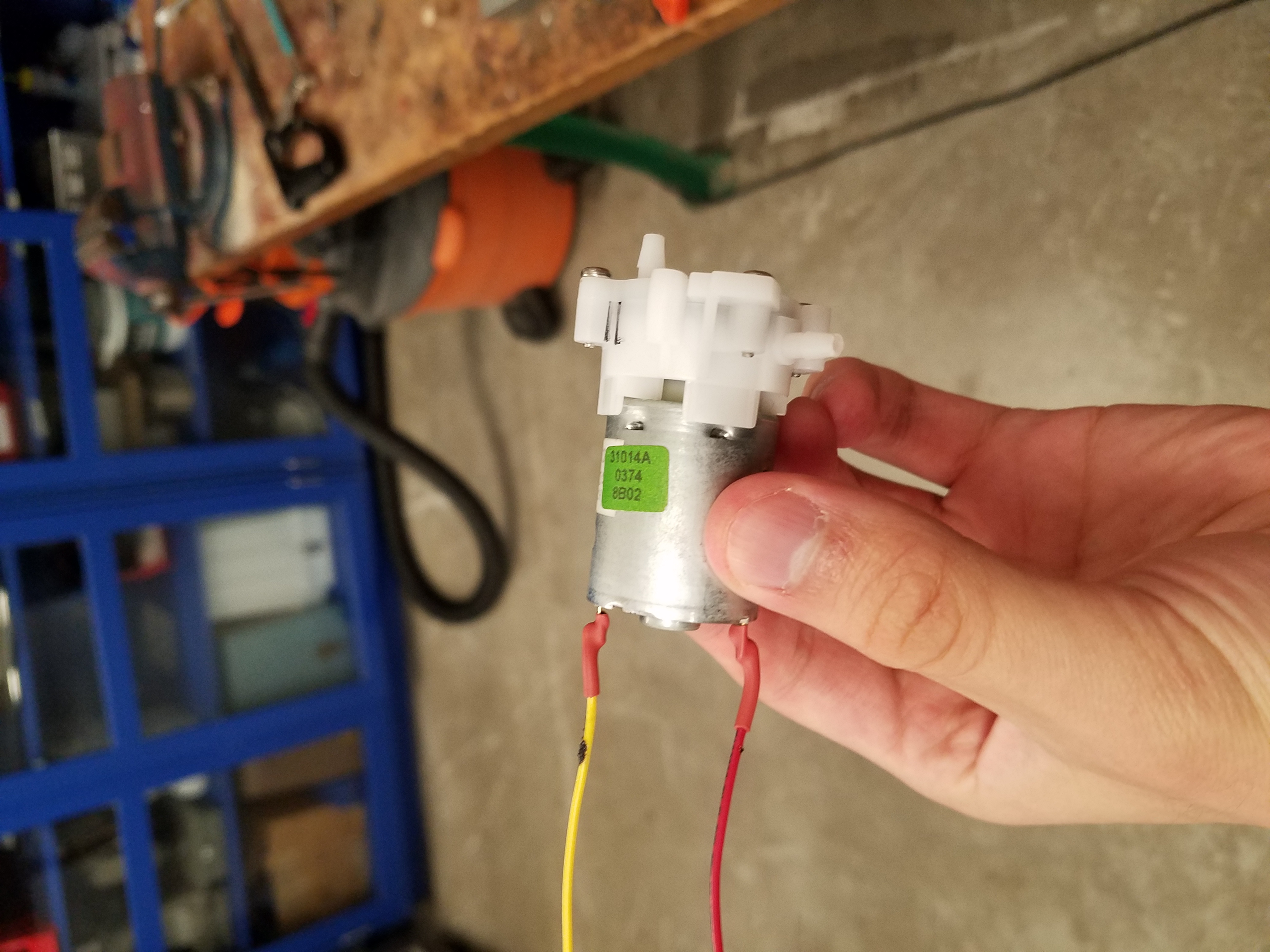
Preparing a Water Pump Motor for Use
Using a razor, I cut some wire and heat shrink tubing. I then stripped the wires using a wire stripper (very appropriate name), and after soldering the wires to the leads of the motor (a skill that I learned in session 1), I used the heat gun to shrink the tubing around the solder points. This increases the robustness of the soldering connections I made, and now the motor is ready to be utilized.
Using an Air Pump to Inflate a Balloon
I prepared an air pump motor in the same way, and used a power supply to use the motor to inflate a balloon:
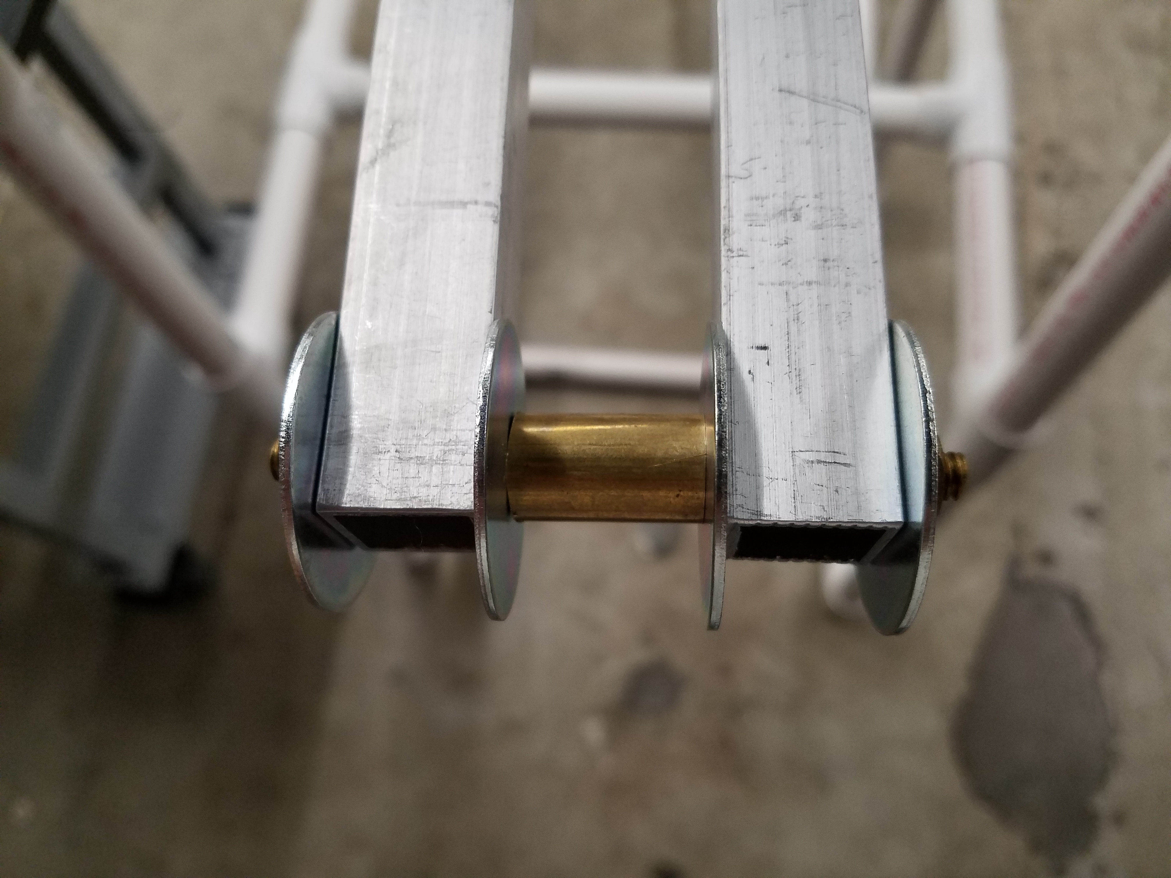
Creating a Brass spacer
I used a hack saw to cut some brass tubing into a spacer that I could use to connect two aluminum bars that I will use for my final project robot. I also used the hack saw to cut a brass threaded rod, and used it in conjunction to the spacer to join the two aluminum bars.
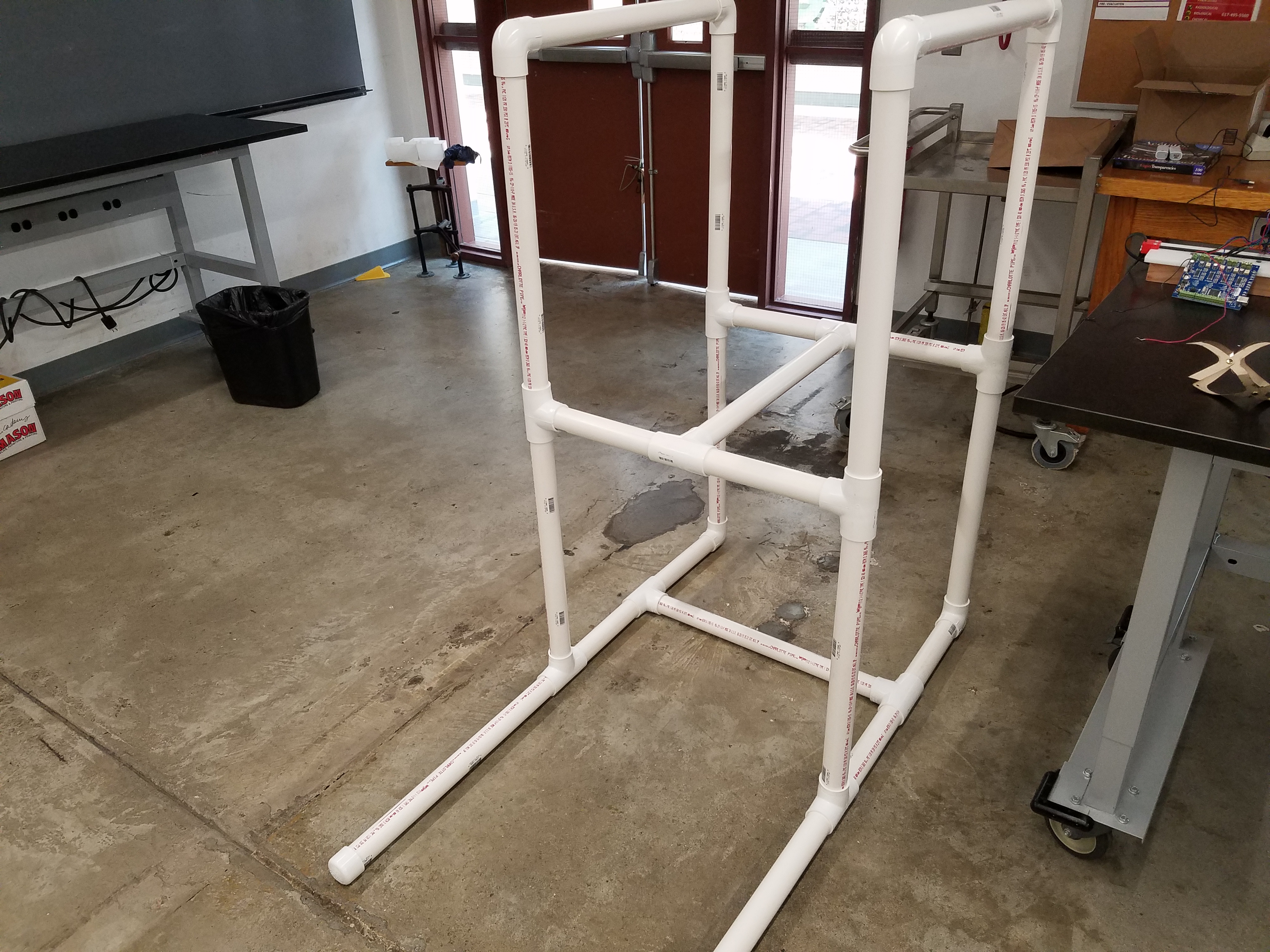
Creating a PVC Stand for my Robot
Since I work at the SEAS Instructional Machine Shop, I have access to a very nice tool known as a horizontal saw. It is ideal for cutting round objects (which a standard band saw has trouble cutting), and it can even be automated.
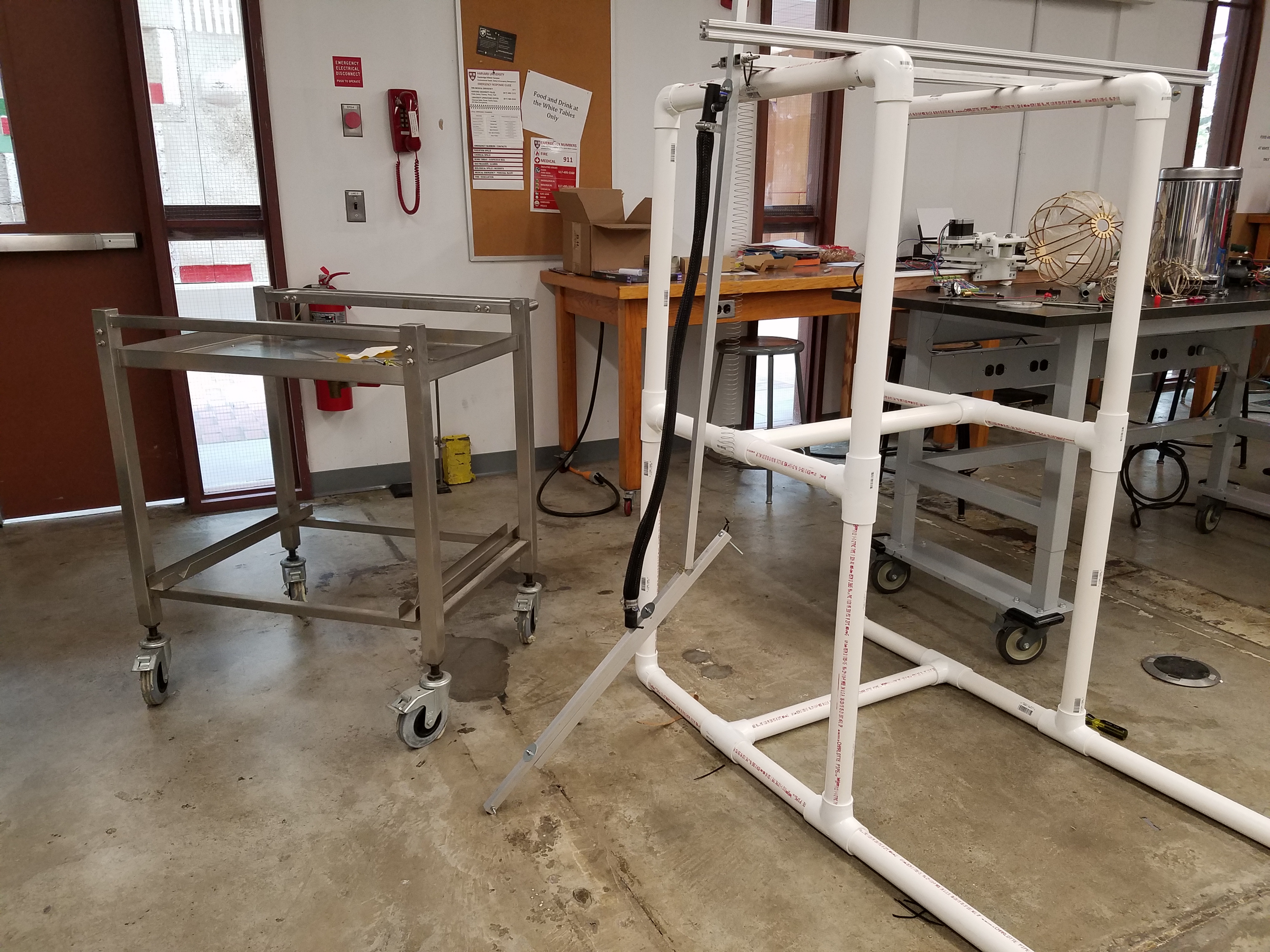
I used the horizontal saw to cut some PVC which I used to make a quick and dirty stand for my pneumatic robot arm, so I don’t have to waste time finding one that’s high enough or build my own out of wood.
I then attached an 80/20 slotted aluminum rod to the top of the stand. I will eventually pivot the robot arm off of a Thor Labs clamp attached to this 80/20 rod. In order to do this, I drilled two holes in two adjacent pipes, and then cut (using the hack saw) and filed down some long screws with a belt sander, so they could fit into a nut just inside the 80/20 slot.
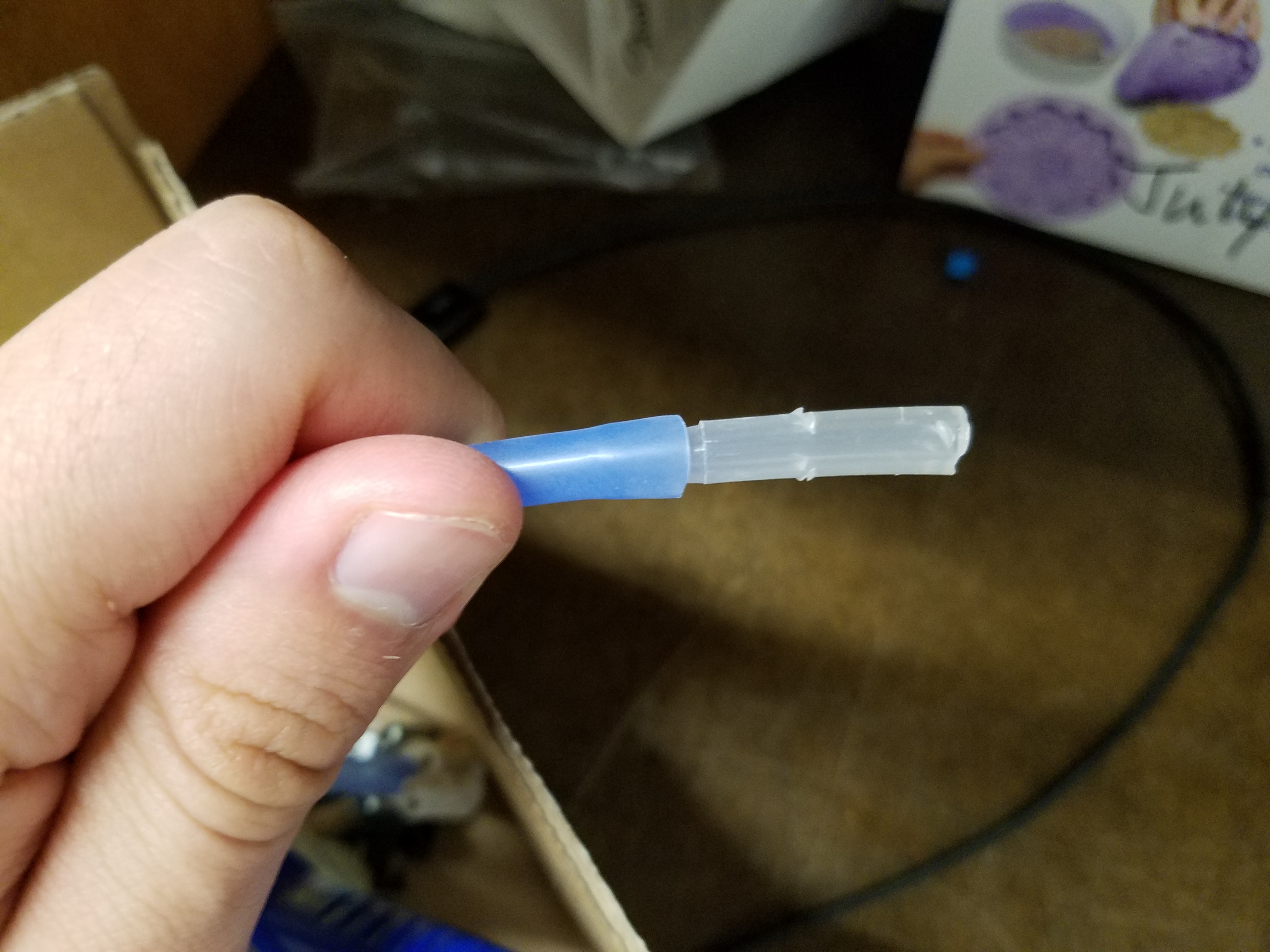
Connecting the Soft Gripper to an Air Tube
It may seem silly to document this, but I’m doing so anyway for the purpose of completing the weekly assignment. So far, the only way to inflate the soft gripper is using the air syringe. I want to be able to control it using the air pump motor. To do this, I used a razor blade to cut some air tube, and I also cut the tip off of a standard lab bottle nozzle, which I can fit the tube around. I can then jam the tube into the opening in the Soft Gripper, since the hard nozzle acts as a syringe needle (as opposed to the soft tubing which cannot be inserted).
Using a Transistor as a Switch
This circuit was actually made during our very first lab section, but I thought it would be more appropriate to document it here.
A transistor acts as a sort of "switch" that can let a large current flow through after expending only a minimal amount of energy. Normally, transistors are used to allow current to flow through its drain and source leads after a small voltage is applied to its gate pin, but I wanted to try something more challenging and wire it so that the opposite happens: applying a signal deactivates the current flow through the drain and the source. In particular, I wanted to be able to press a pushbutton and turn off an LED as opposed to turning it on as a sort of "inverse" switch.
The schematic for the circuit is as follows:
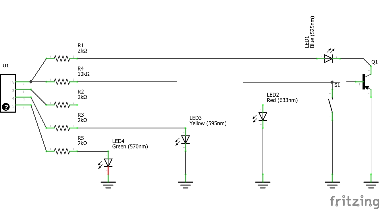
I am powering my circuit with an Arduino Uno, which I can program to cause the LED to do some nifty tricks. The LED I want to turn off with my transistor is controlled by a pin that pulses, causing the light to flash. I also hooked up some red, green, and yellow LEDS to other pins (outside of the transistor circuit) in a "traffic light" configuration and programed the Arduino to alternate them.
Here is a video of the entire circuit in action:
The code I used is a modified version of Aurduino’s sample code "Blink:"
int led_green=5;
int led_yellow=4;
int led_red=3;


// the setup function runs once when you press reset or power the board
void setup() {
  // initialize digital pin LED_BUILTIN as an output.
  pinMode(LED_BUILTIN, OUTPUT);
}

// the loop function runs over and over again forever
void loop() {
  digitalWrite(LED_BUILTIN, HIGH);   // turn the blue LED on (HIGH is the voltage level)
  delay(100);                       // wait for a second
  digitalWrite(LED_BUILTIN, LOW);   // turn the LED off
  delay(100);                       //etc.
  digitalWrite(LED_BUILTIN, HIGH);
  delay(100);
  digitalWrite(LED_BUILTIN, LOW);
  delay(100);
  digitalWrite(LED_BUILTIN, HIGH);
  delay(100);
  digitalWrite(LED_BUILTIN, LOW);
  delay(1000);
  digitalWrite(led_green, HIGH);
  delay(200);
  digitalWrite(led_yellow, HIGH);
  delay(200);
  digitalWrite(led_red, HIGH);
  delay(200);
  digitalWrite(led_green, LOW);
  delay(200);
  digitalWrite(led_yellow, LOW);
  delay(200);
  digitalWrite(led_red, LOW);
  digitalWrite(LED_BUILTIN, LOW);
}
Using the Voltage Multimeter
As you can see in the video, the blue LED is much brighter than the red, yellow, and green LEDs. I used the voltage meter to see if I can determine why this may be.
Measuring the resistance on all four LED-resistor pairs yields the same value:
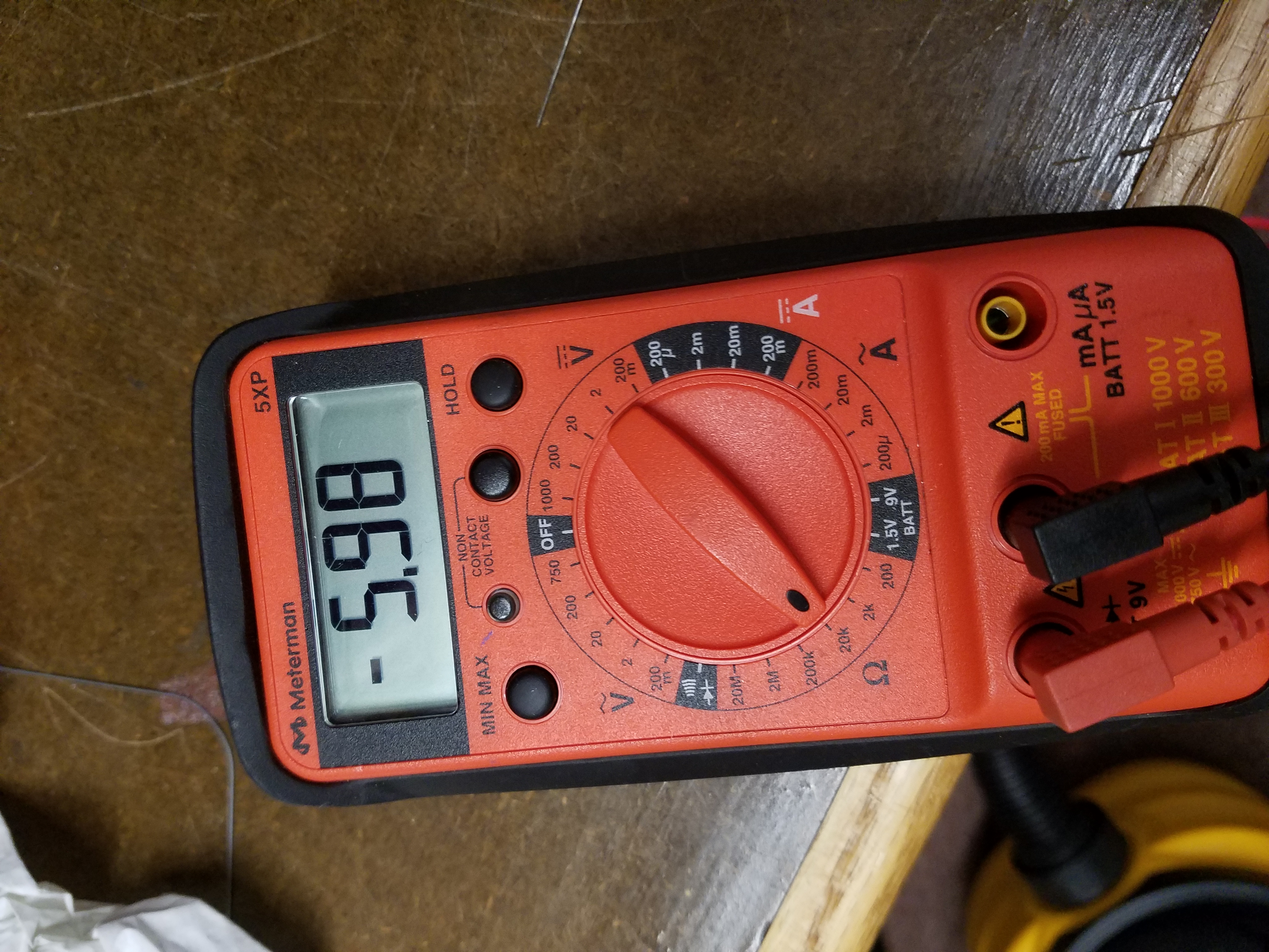
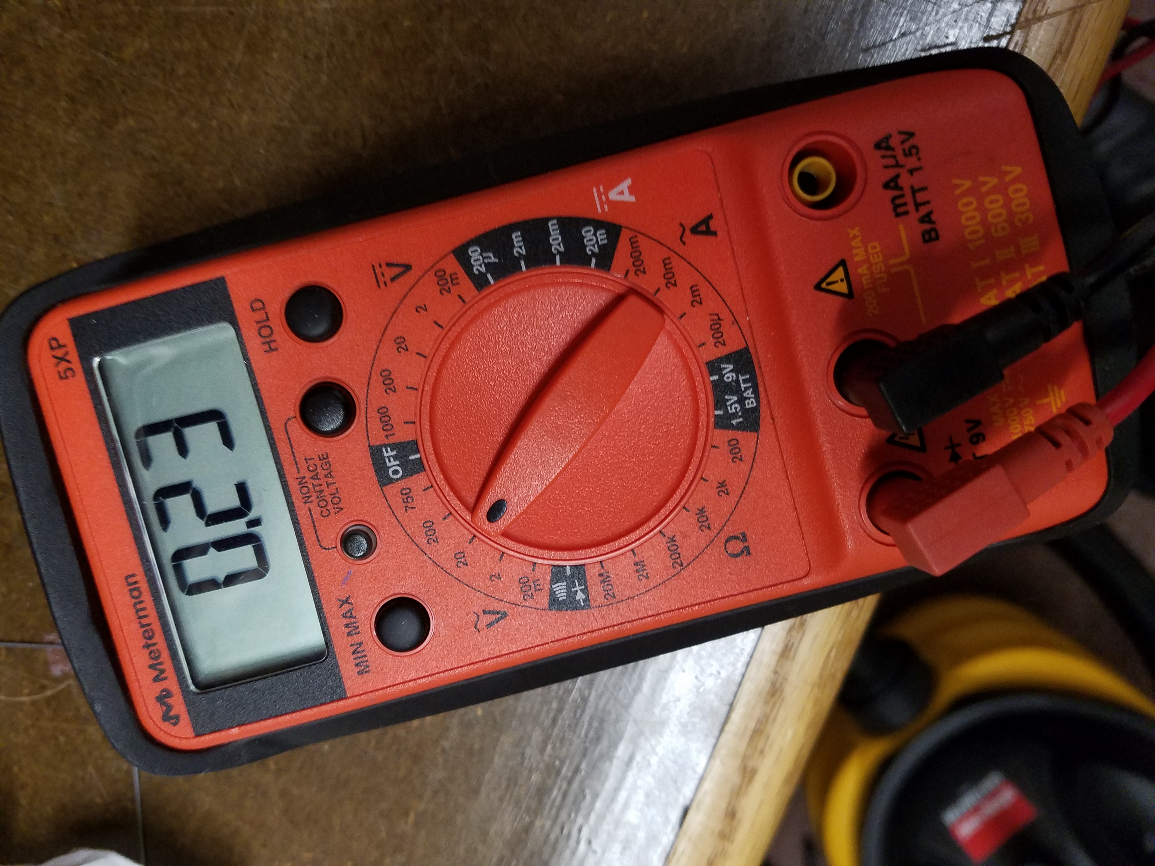
However, measuring the voltage is another story. The voltage for the blue LED goes pretty high:
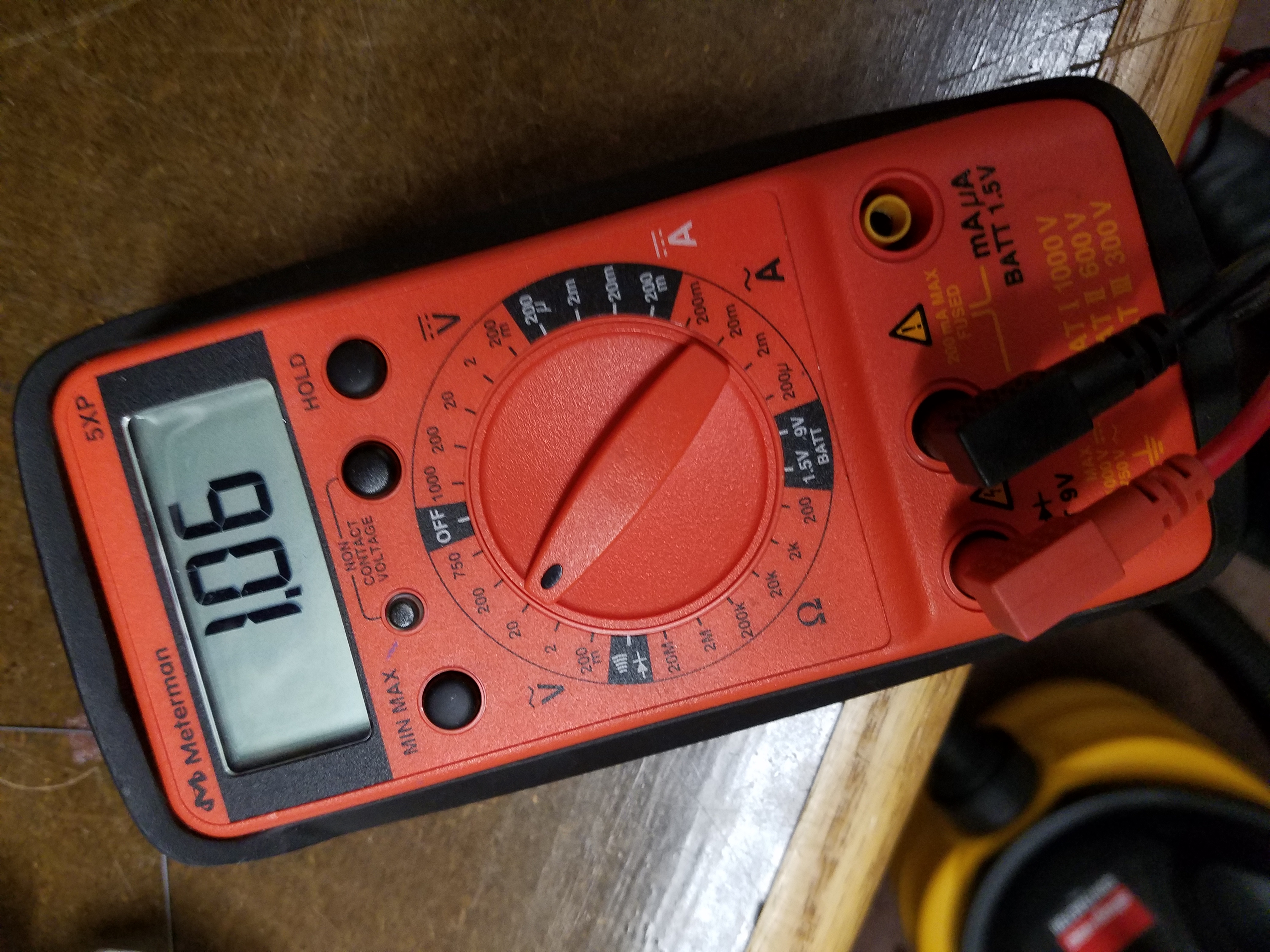
The voltage on the other three dimimer LEDs doesn’t go nearly as high: