06: 3D Design & Printing
Assignment
-
Design and print a small object that could not be (easily) made by subtractive methods. Discuss pros and cons of 3D printing this object rather than using other fabrication methods.
-
Scan something.
-
Please read the following to preview for next week:
- Sparkfun’s Intro to Capacitance
- Jonathan Grinham’s Capacitive Plants
- Matt Keeter’s Capacitive Multitouch
3D Printing an Air Hose Connector
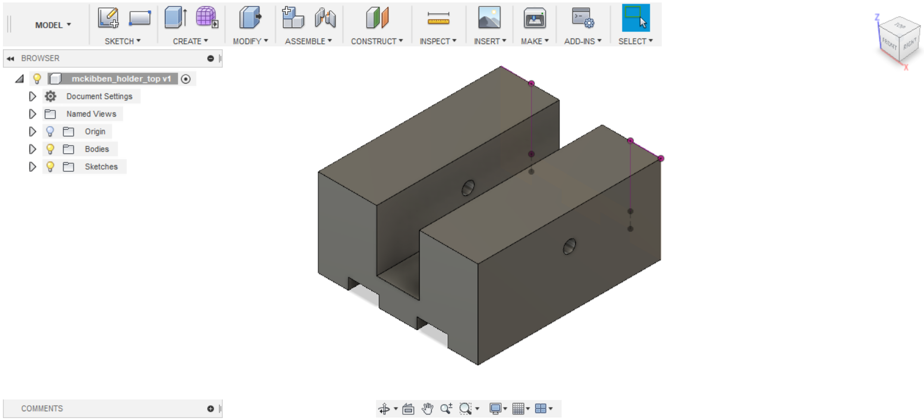
Rather than spending the three dollars needed to buy one of these connectors, I decided to try 3D print my own by designing it in Fusion 360 (.stl file can be found here):
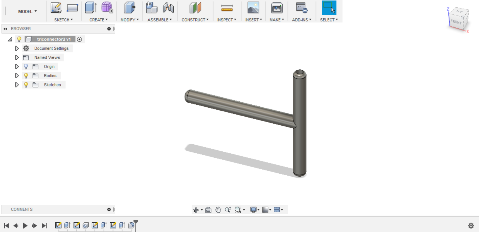
I made this shape by making two circles within each other and extruding this into the third dimension. With the use of some construction lines, I created a hole in the center of the tube and repeated the process at a 90 degree angle. I then converted this model into an .stl file, and then used the Cura program to convert it into an Ultimaker file. I then used an SD card to give this file to the Ultimaker 3D printer:
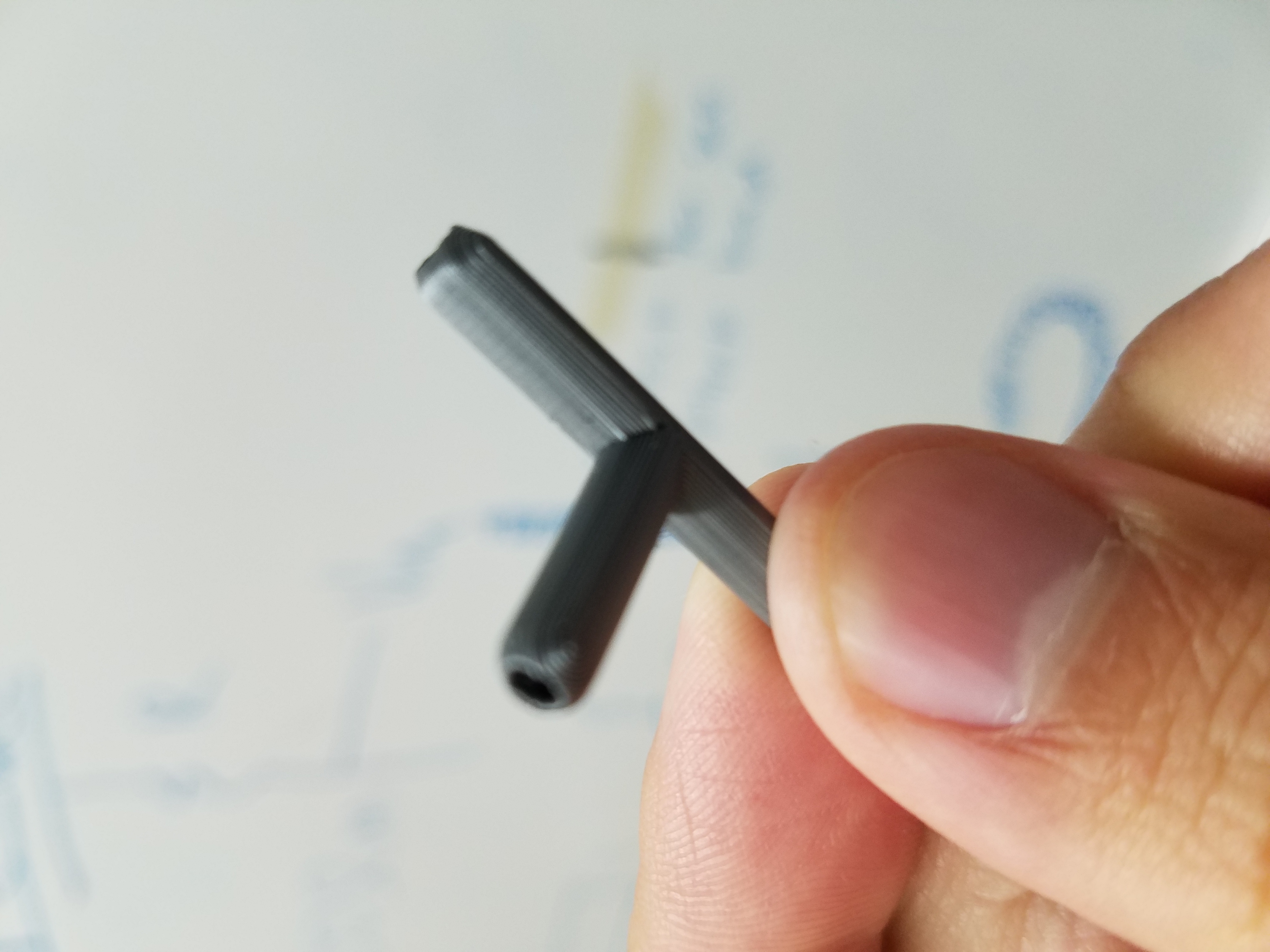
Unfortunately, the finished part leaked air and did not serve as a suitable replacement for the part I can buy. The problem with this air connector seemed to be two-fold: the connector itself is too thin and may have leaking points, and the “support raft” printed underneath the connector didn’t detach perfectly and left bumps on the surface which could push the tubing up enough to cause leaks.
So, I designed a better version of the connector in Fusion 360 (.stl can be downloaded here) with thicker walls and with slightly better symmetry.
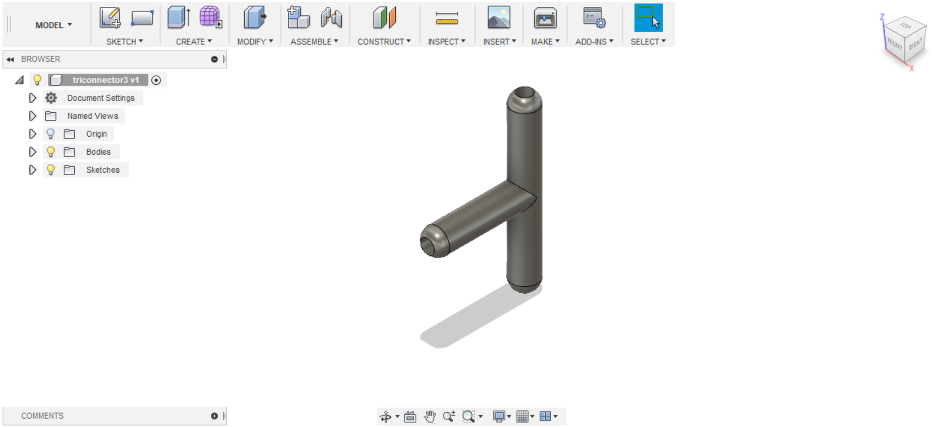
I also switched to a different printer (the Prusa MK3) and adjusted the slicer settings so it did not print the “support raft.” This seemed to do the trick:
There are no bumps on this one as a result, and it worked airtight like I wanted!
3D Printing a Mold for the Soft Gripper
The existing soft gripper did not pump air uniformly into its four fingers, which I suspect is a result of imperfections due to the silicone not being distributed uniformly during the molding process. To fix this problem, I decided to 3D print my own mold, which should be much more rigid compared to the cardboard and hot-glue mold suggested by the Soft Robotics Toolkit website.
Luckily, I found that someone had already conveniently designed a mold for this very gripper and freely offered the .stl file on their blog. Therefore, it was just a matter of converting this file using Cura and feeding it into the Prusa 3D printer:
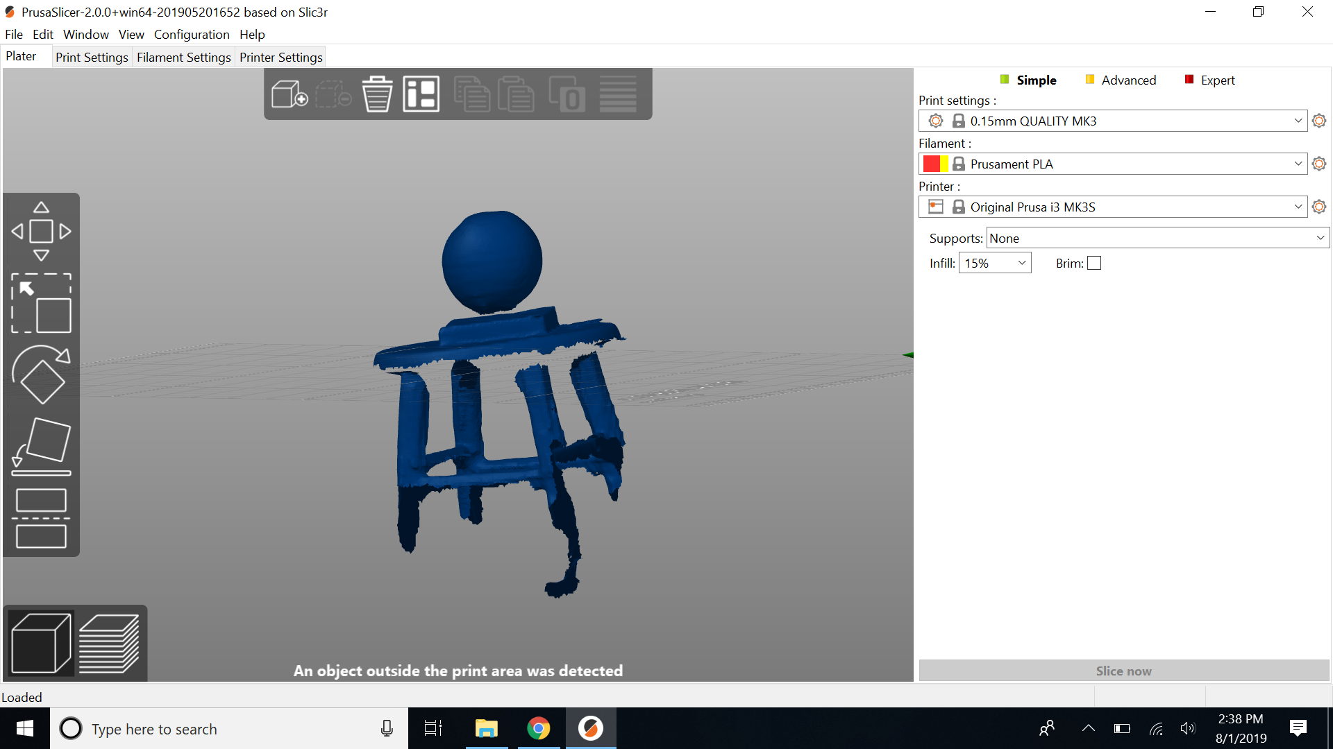
Unfortunately, the 3D printer had some issues printing the mold, as you can see in the video. The mold was printed off-center, and a portion of the “support raft” was missing on the bottom, causing the mold to come out misaligned:
It turned out the problem was the 3D slicer I was using. The Ultimaker Cura doesn’t seem to like slicing things for the Prusa MK3, so I resliced it using the Prusa Slicer instead. After all, it would make sense to use the slicer made for the specific printer I’m using.
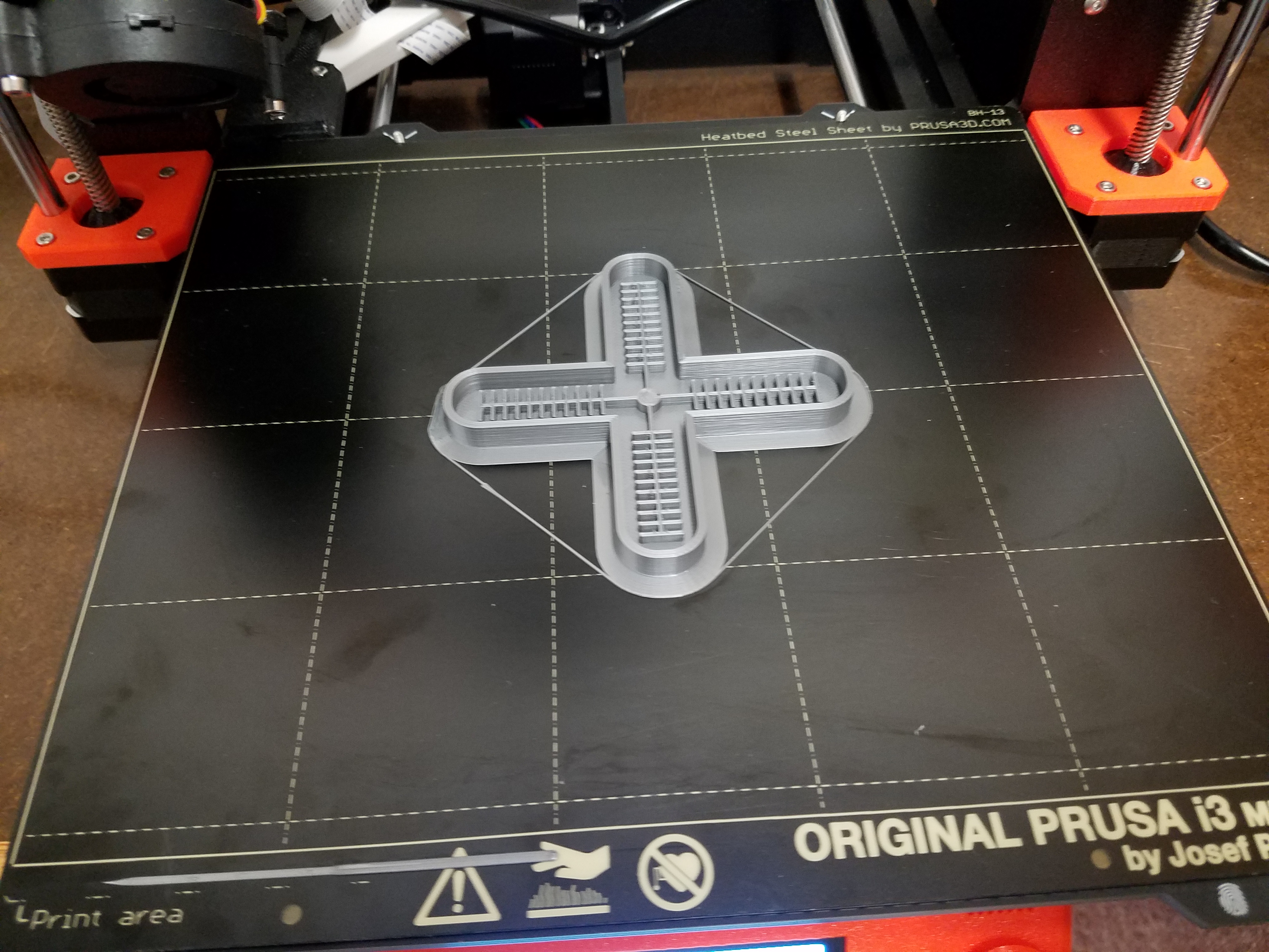
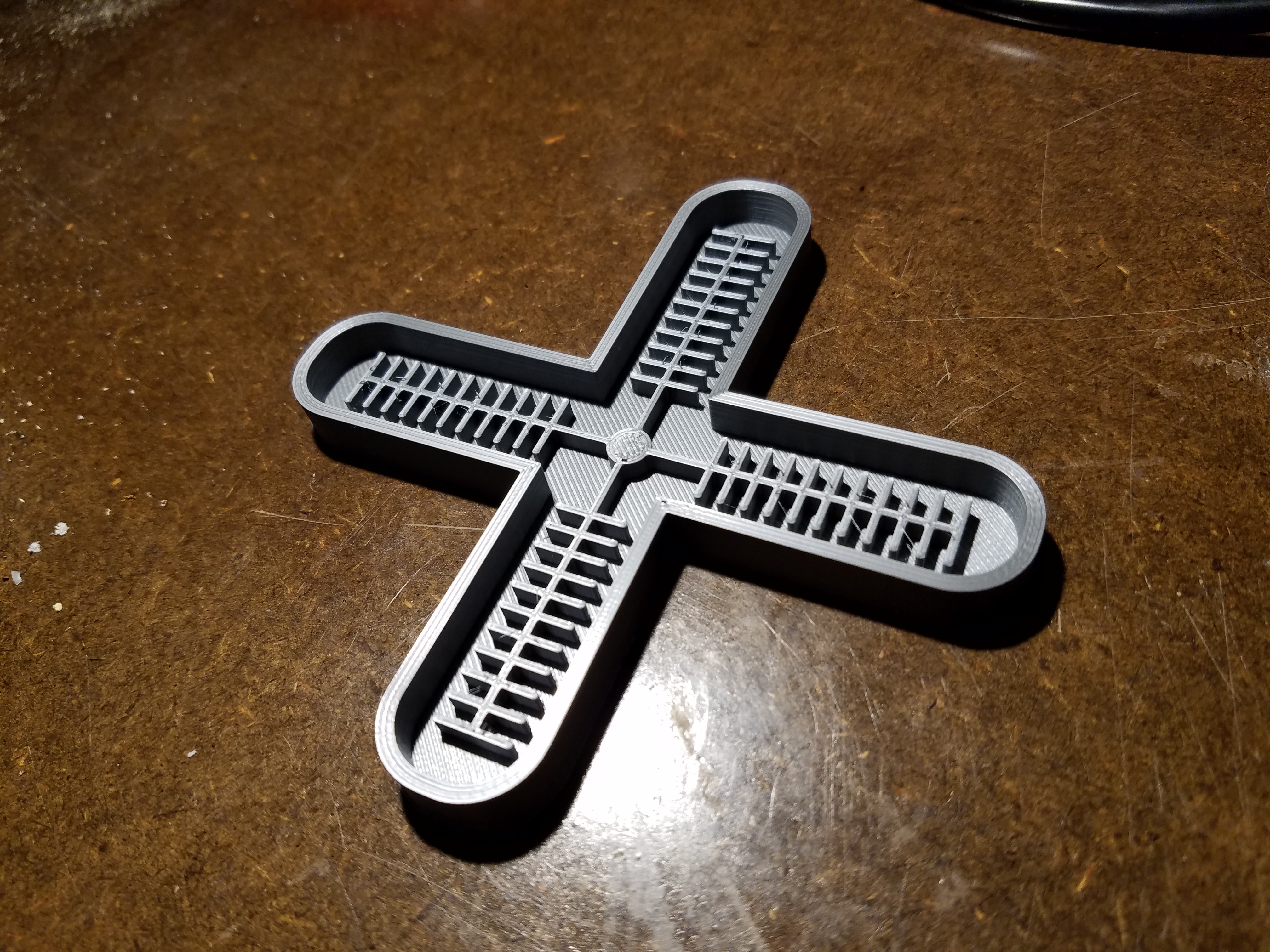
This time, the mold printed correctly, as you can see by the mold appearing in the middle and being within the printed boundary markers. The mold turned out pretty nicely:
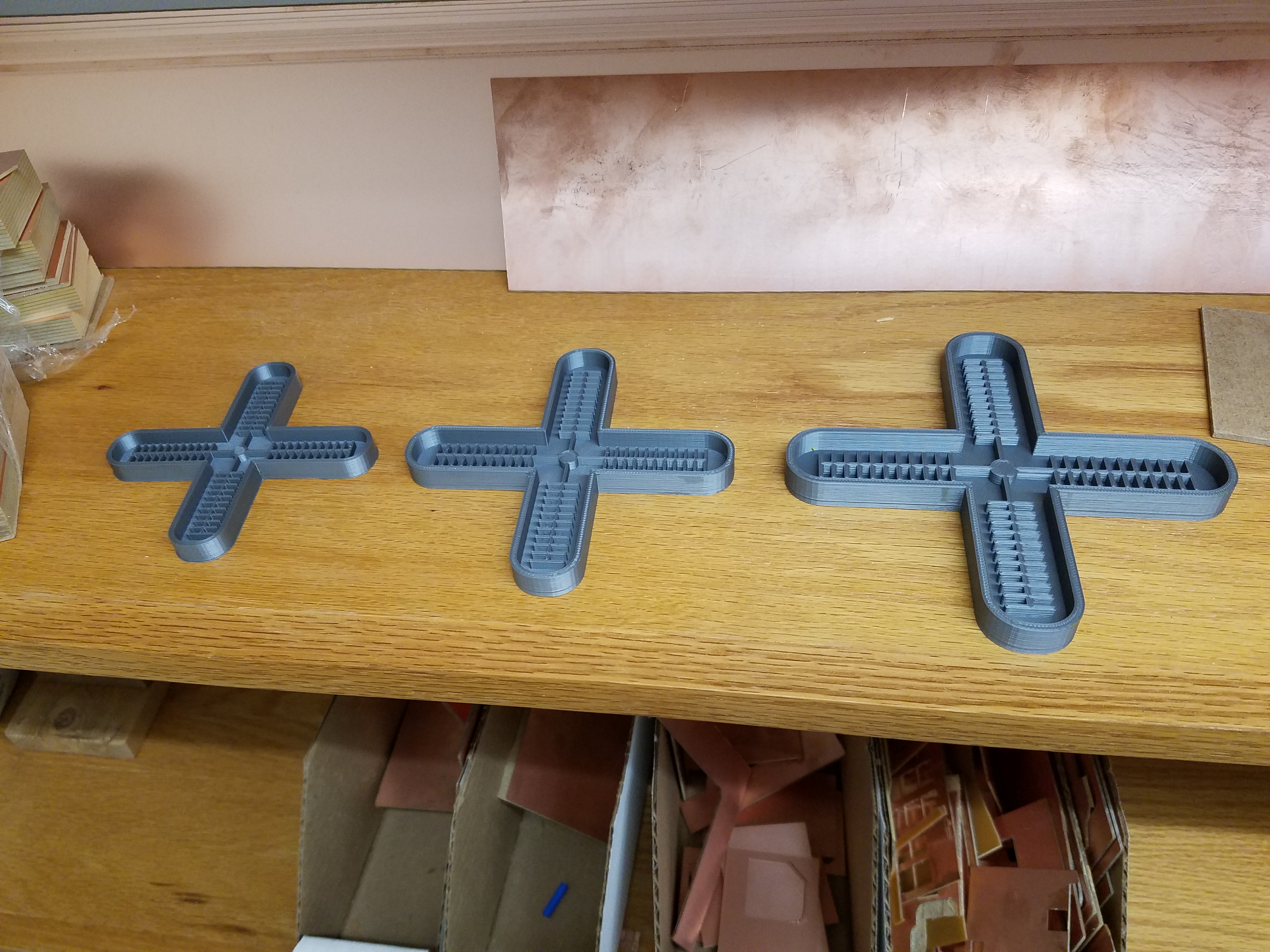
However, the gripper that would result from this mold would be really tiny. I experimented with changing the size on the Prusa Slicer to produce larger variants of this mold.
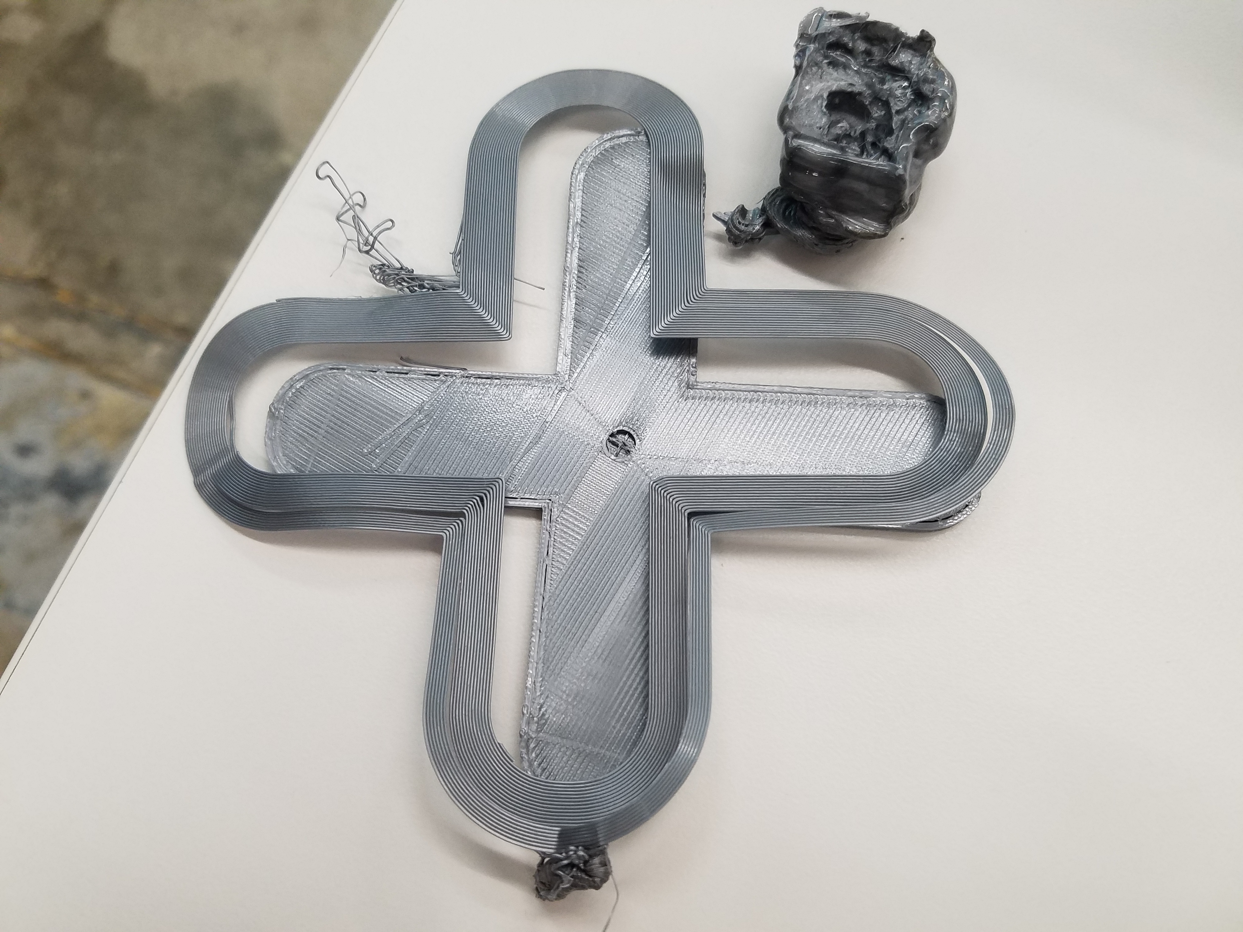
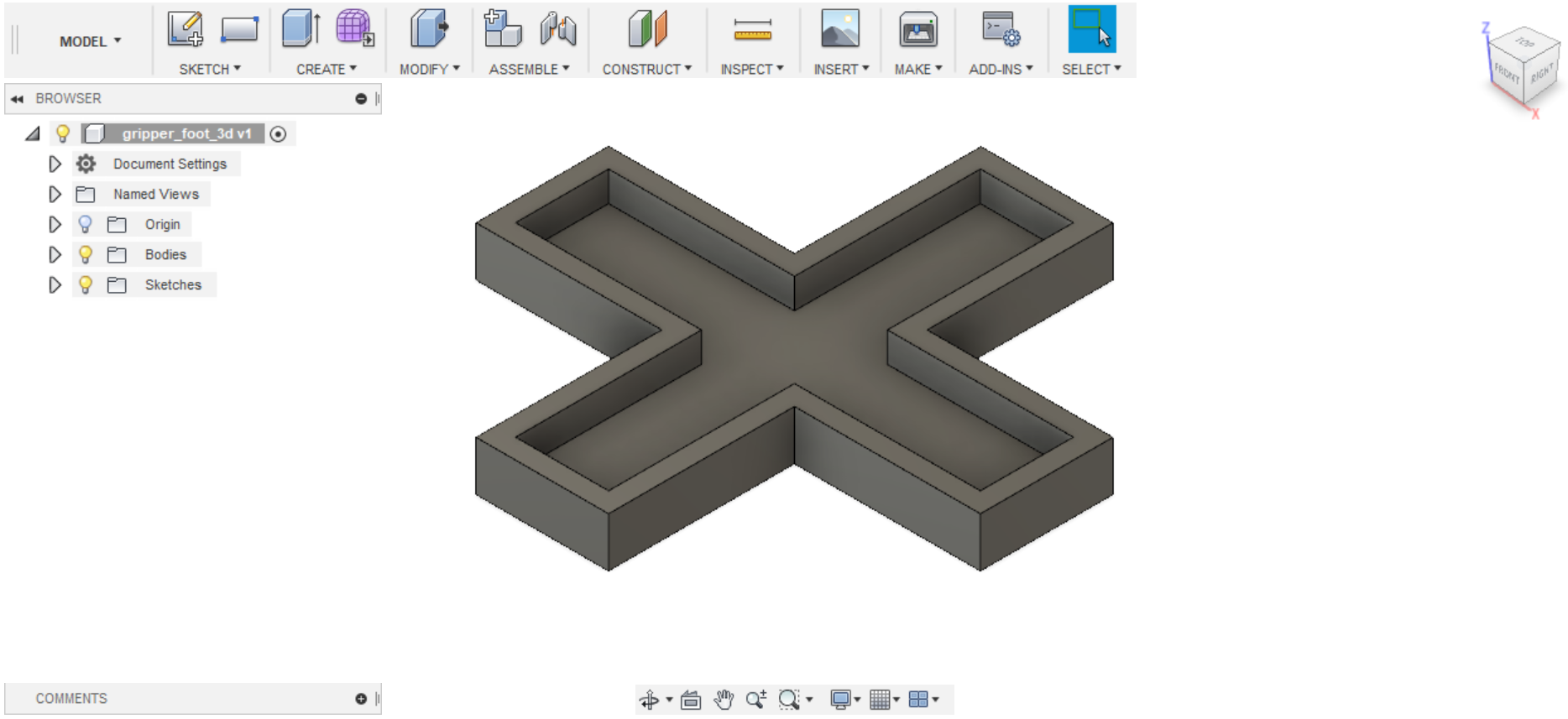
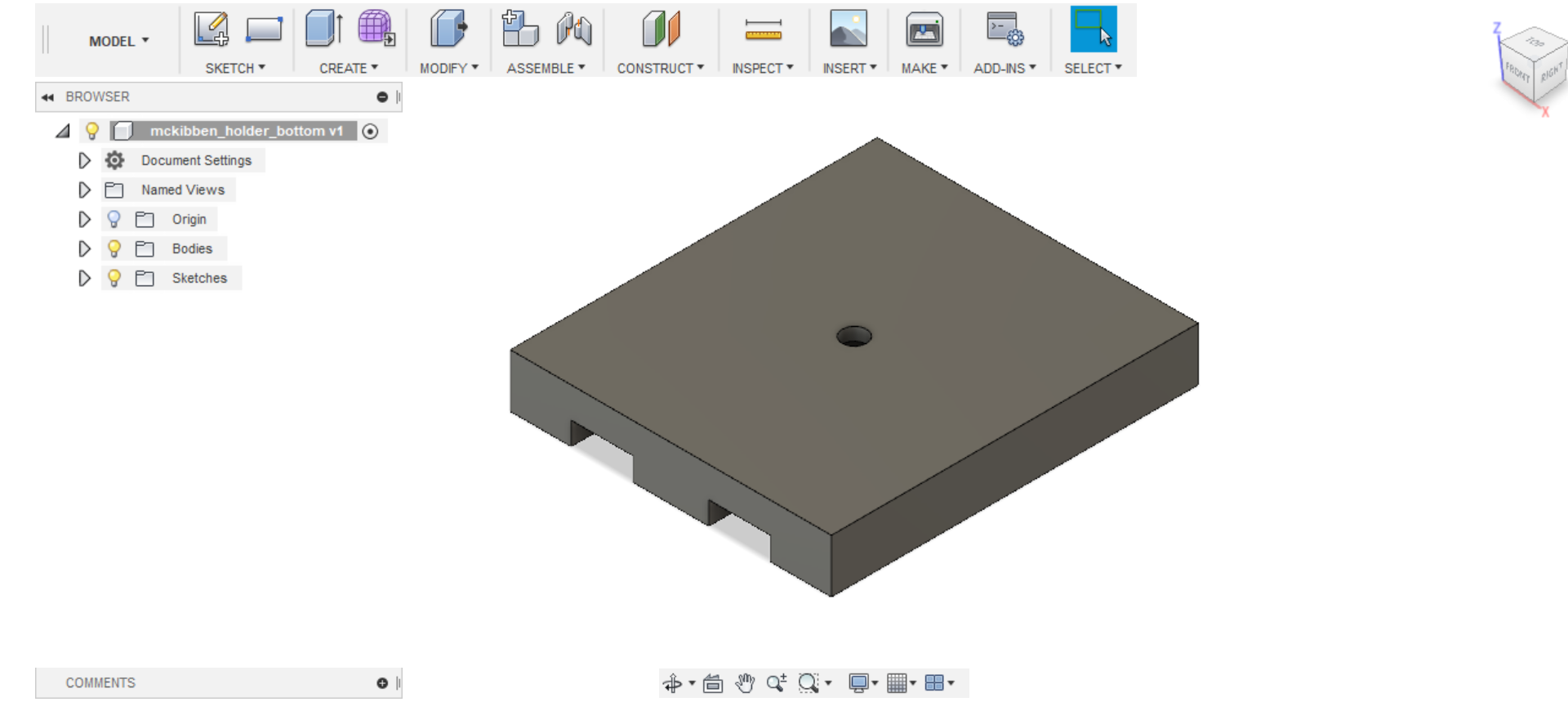
I also designed my own mold in Fusion 360 for the bottom half of the soft gripper, which is simply a cross roughly in the same dimensions as the largest version of the upper-half mold. You can download an .stl of this mold here.
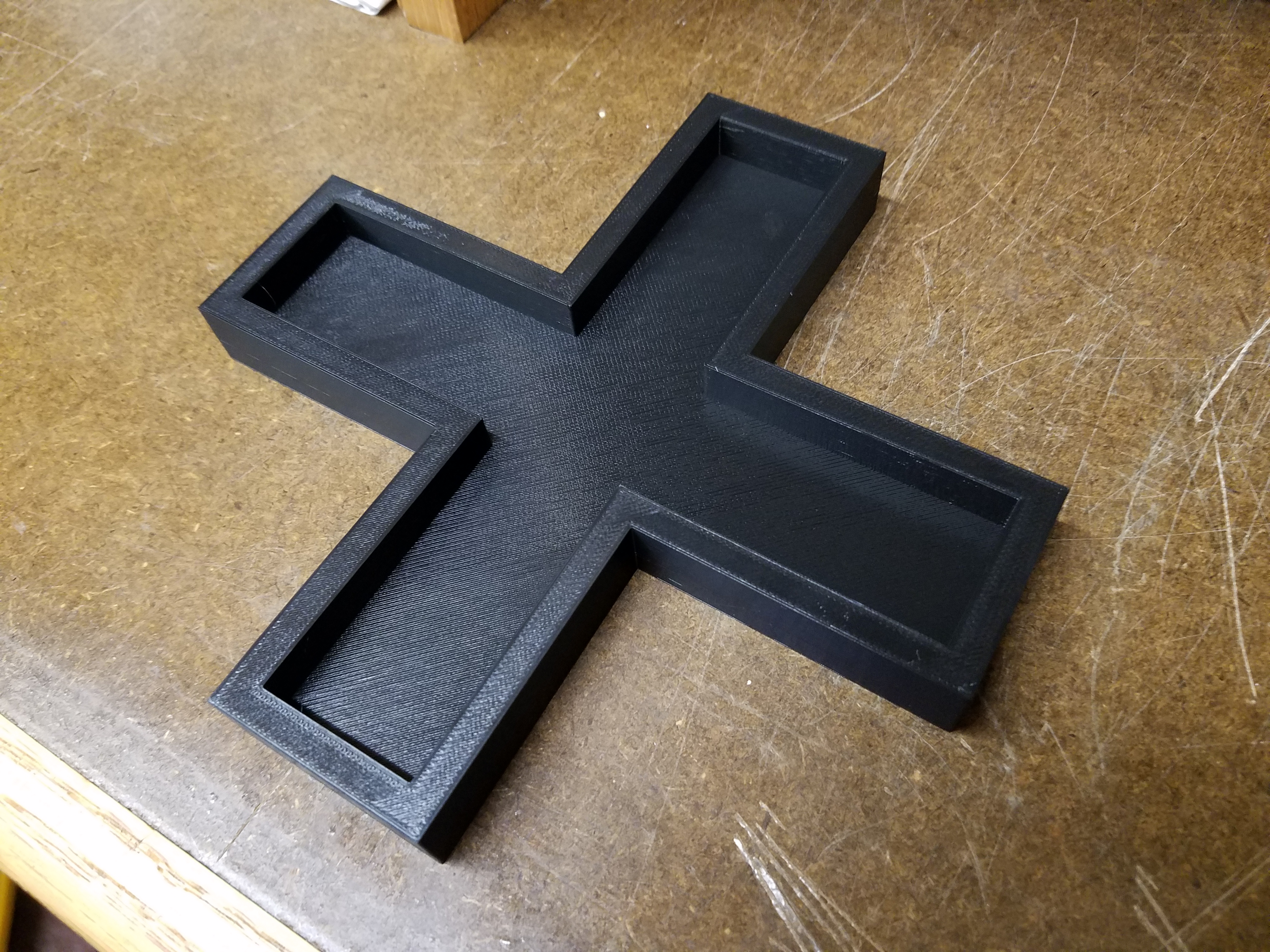
While 3D printing the air-hose connector was done more in the interest of time than anything else, I think a good case can be made for justifying the 3D printing of the molds. As I said earlier, I need the mold to be as precise as possible, and I don’t think making one out of cardboard would cut it. 3D printing the bottom half also allows me to save time and not have to worry about using a knife to cut out a perfect cross shape from a larger sheet of silicone.
3D Printing Miscellaneous Parts
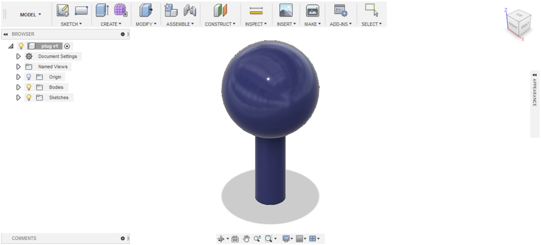
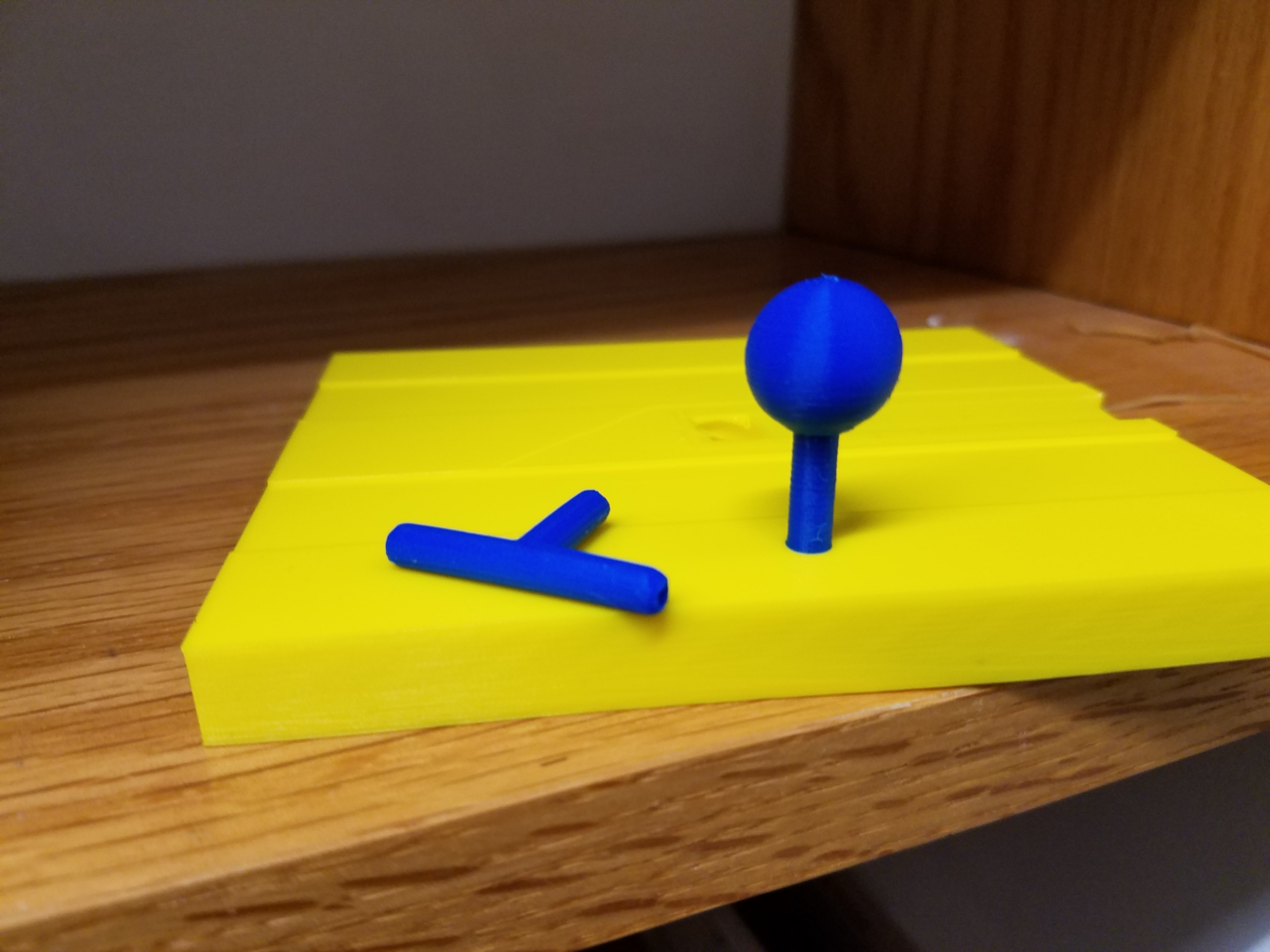
I 3D printed some various parts to use for my final project. These include two clamping mechanisms for my arm, a tube stopper, and a cylindrical spacer (.stl downloads here, here, here and here respectively).
Clamping mechanism:
Stopper:
Spacer:
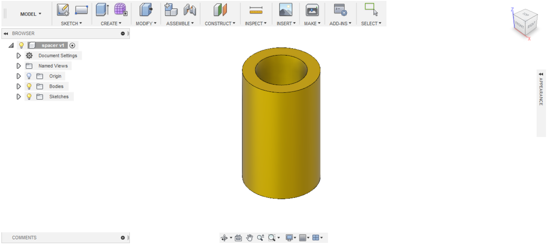
The spacer and the stopper turned out nice, and I made them in some pretty blue and yellow colors to boot. I also printed out a blue version of the air-hose connector.
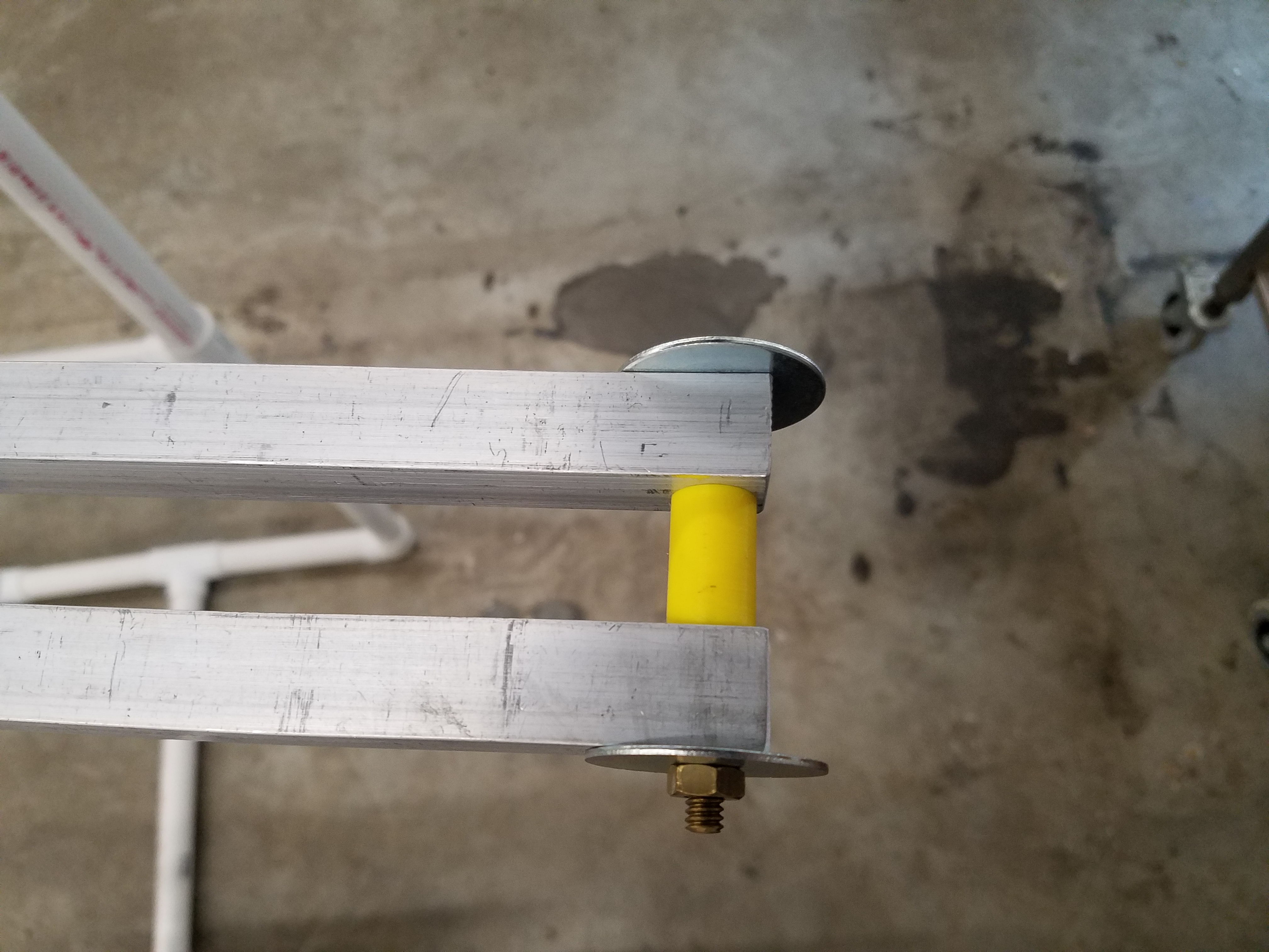
I replaced the brass spacer I made for session 2 with the 3D printed version, since I would prefer the spacer to be precisely even, which is hard to achieve by filing a brass spacer down, and machining a perfect spacer with a mill would be time consuming (in contrast, the 3D printer made what I needed in a few minutes!).
However, the clamp did not turn out well. For some reason, the printer lost its grip on the filament and went through the rest of the printing motions without actually printing the rest of the object. I suppose this is for the best, since the part needs to be at 100% infill because of the stress this clamp would be under, and that would have wasted a lot of material. My only justification for printing this particular part is that the 3D printer is the only tool I have access to outside of lab hours.
I opted to machine the clamp instead, which you can be read about in session 11.
3D Scanning a Levitating Sphere
I wanted to try something a little bit different with 3D scanning. 3D scanning can’t capture every possible perspective of a given object, such as the area touching the ground, but what if this object was levitating?
I wanted to see if I could capture the entire surface of this levitating globe. To do this, I need to first cover the globe in masking tape, since the 3D scanner has difficulty sensing a reflective surface.
Oddly enough, despite the fact that the levitating globe rotated on its own, the 3D scanner could not seem to recognize the fact that it was spinning and so only imaged a hollow hemisphere. I tried placing a square object on top of the globe to see if this was an issue with the sphere shape itself, and I also wrote letters on the tape, but this didn’t fix it either. So I simply walked around the globe myself and captured every angle I could. This did the trick, since the 3D scanner was able to tell from the background moving that I was walking to the backside of the globe.
Here is the model (.stl can be download here) created by the 3D scanner, which you can zoom in and rotate:
It did pretty well, though not completely perfect, as there is still a tiny gap at the very bottom. Still, this was an interesting experiment nonetheless. I don’t think too many people can say they have 3D scanned a levitating object in their lifetime.