09: Electronic Output Devices
Assignment
Choose an output device that you have not used before. Program an Arduino to operate it.
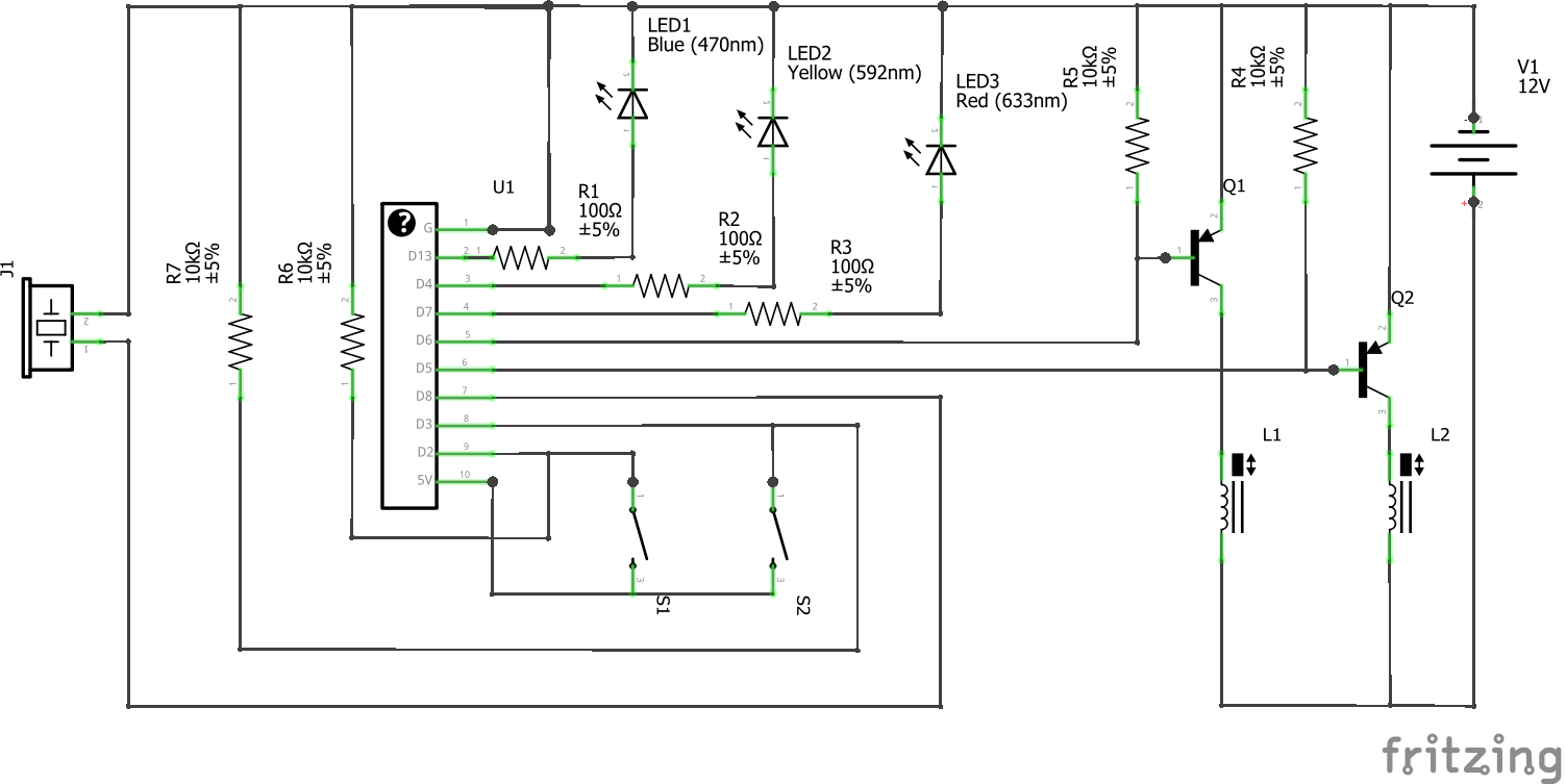
Controlling the Air Valves
I created a circuit for the Arduino Nano that allows me to control two air valves with two pushbuttons. Each pushbutton activates one of the solenoid valves and lights up an LED (blue for air pressure, yellow for release like in 05: Programmablee Electronics). If both pushbuttons are pressed at the same time, a red LED will light and a buzzer will sound, since this would be an invalid command (i.e. commanding the robot arm to move up and down at the same time), and would waste air.
Here is a schematic of the circuit:
Here is the program I used:
// constants that don't change
const int buttonPin = 2;     // the number of the pushbutton pin
const int releasePin = 3;

const int ledPin =  13;      // the number of the LED pin
const int releaseLedPin = 4;
const int warningLedPin = 7;

const int valve = 5;
const int releaseValve = 6;
const int buzzer = 8;

// variables that will change
int buttonState = 0;         // variable for reading the pushbutton status
int releaseState = 0;

void setup() {

  // initialize the pushbutton pins as inputs:
  pinMode(buttonPin, INPUT);
  pinMode(releasePin, INPUT);

  // initialize the LED pins as outputs:
  pinMode(ledPin, OUTPUT);
  pinMode(releaseLedPin, OUTPUT);
  pinMode(warningLedPin, OUTPUT);

  // initialize valve controls as outputs:
  pinMode(valve, OUTPUT);
  pinMode(releaseValve, OUTPUT);
}

void loop() {
  // read the state of the pushbutton value:
  buttonState = digitalRead(buttonPin);
  releaseState = digitalRead(releasePin);

  // check to see which button is pressed. If both pressed, give warning signal
  if (buttonState == HIGH && releaseState == LOW) {

    digitalWrite(ledPin, HIGH);
    digitalWrite(valve, HIGH);
    digitalWrite(releaseLedPin, LOW);
    digitalWrite(releaseValve, LOW);
    digitalWrite(warningLedPin, LOW);
    digitalWrite(buzzer, LOW);

  } else if (buttonState == LOW && releaseState == HIGH) {

    // turn LED off:
    digitalWrite(ledPin, LOW);
    digitalWrite(valve, LOW);
    digitalWrite(releaseLedPin, HIGH);
    digitalWrite(releaseValve, HIGH);
    digitalWrite(warningLedPin, LOW);
    digitalWrite(buzzer, LOW);

  } else if (buttonState == HIGH && releaseState == HIGH) {

    digitalWrite(ledPin, LOW);
    digitalWrite(valve, LOW);
    digitalWrite(releaseLedPin, LOW);
    digitalWrite(releaseValve, LOW);
    for (int i = 1; i <= 20; ++i) {
      digitalWrite(warningLedPin, HIGH);
      tone(buzzer, 650+13*i, 5);
      delay(5);
      digitalWrite(warningLedPin, LOW);
      delay(5);
    }


  } else {

    digitalWrite(ledPin, LOW);
    digitalWrite(valve, LOW);
    digitalWrite(releaseLedPin, LOW);
    digitalWrite(releaseValve, LOW);
    digitalWrite(warningLedPin, LOW);
    digitalWrite(buzzer, LOW);

  }

}
Making an Elbow
I connected my circuit and air valves to a rudimentary setup I made for my robotic arm’s elbow. The McKibben actuator driving the elbow is powered by an air tank, and the air flow is controlled by the two solenoid valves, with one acting as a pressure release.
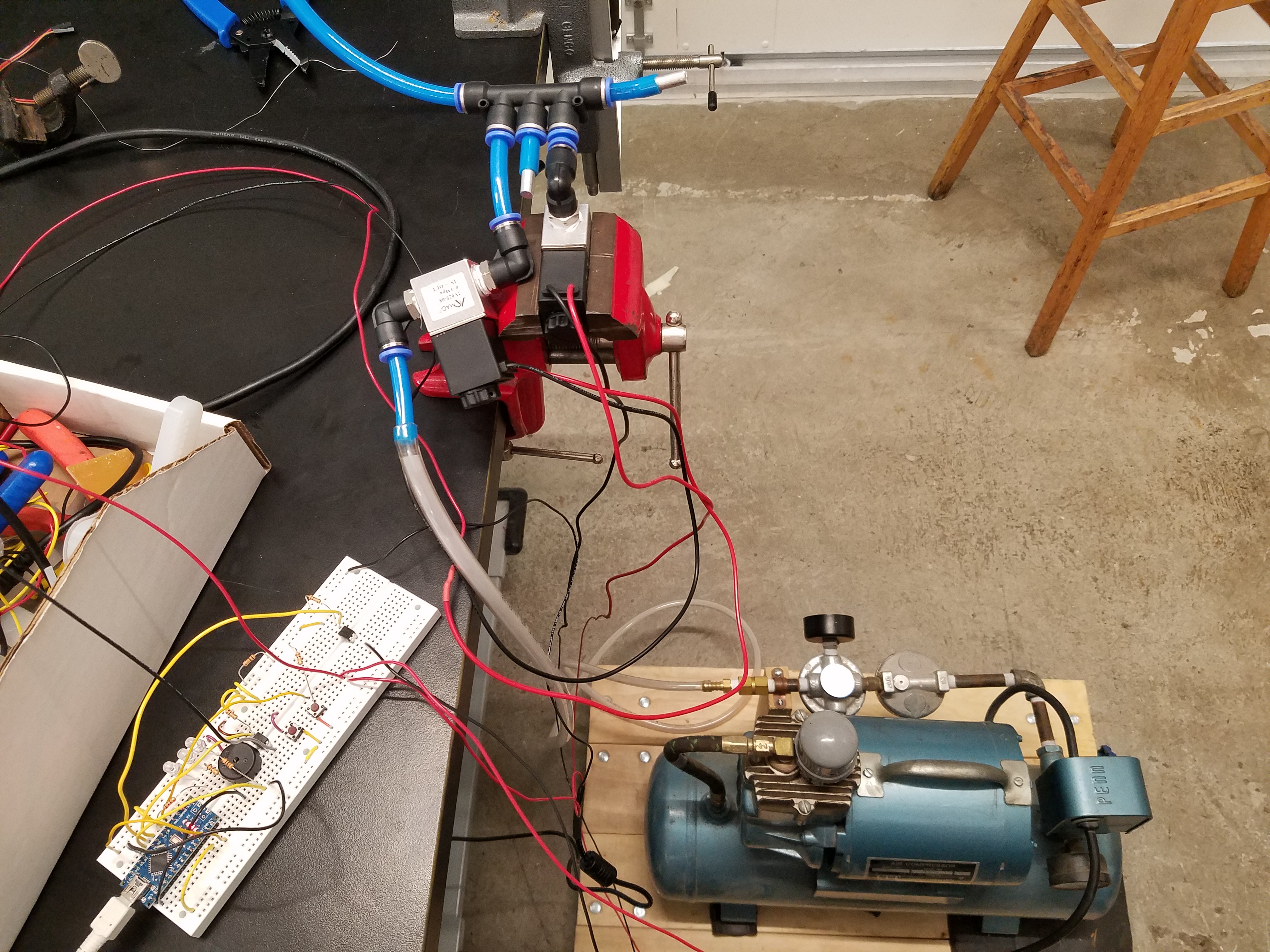
I did a quick test of the actuator setup, which you can observe in this video:
As you can see, pressing one button causes one valve to open (allowing air from the tank to fill the McKibben actuator), while pressing the other button opens the pressure release valve (causing air to evacuate the actuator). Pressing both buttons at the same time plays a warning sound and ceases all movement of the arm.