Final Project
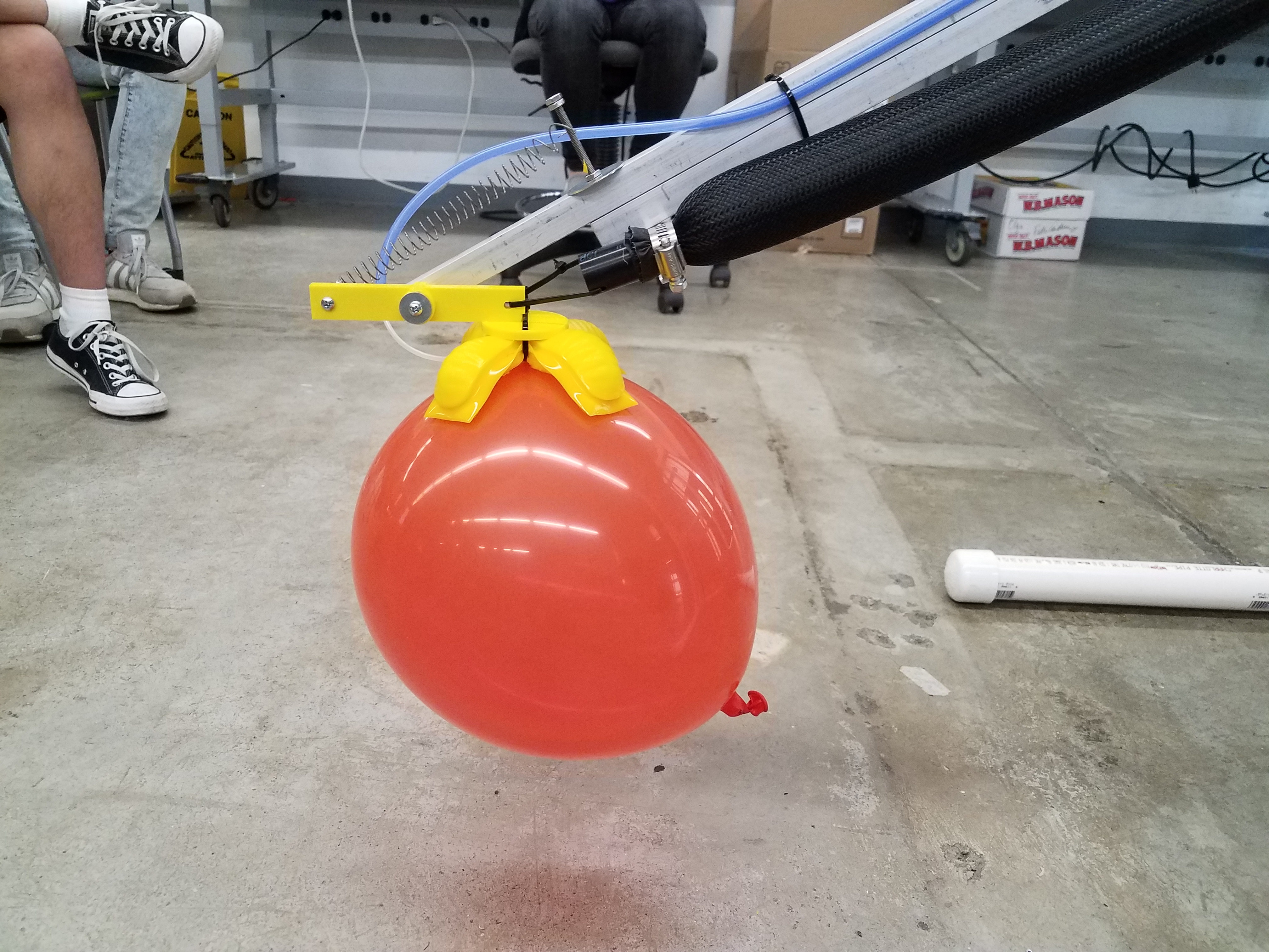
This robotic arm is completely driven by air, and has four degrees of freedom. It uses three McKibben actuators and one pneumatic cylinder to displace the joints of the robot, while the hand is a soft robotic silicone gripper that closes when inflated.
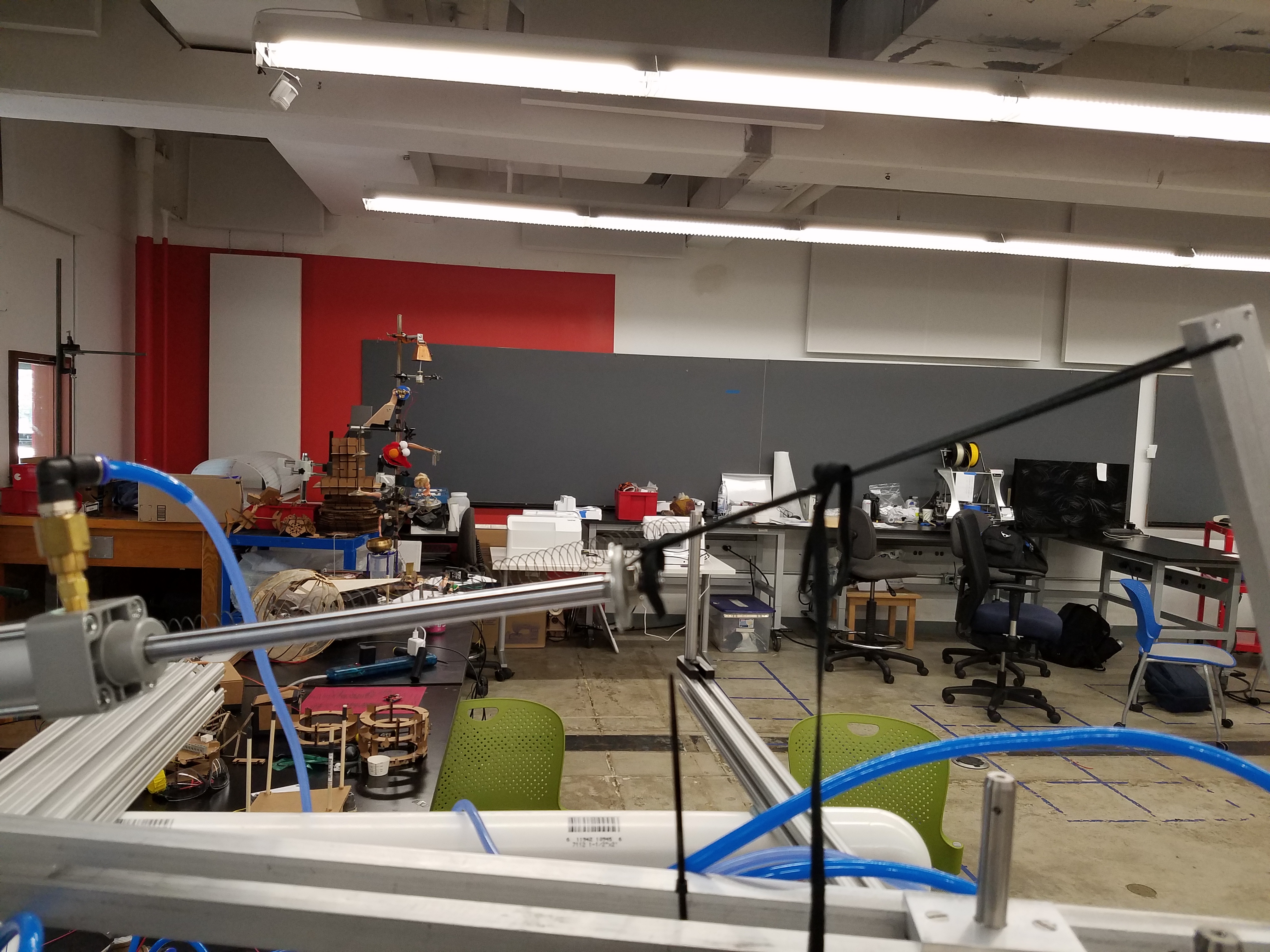
The robot is roughly the size of a person, made mostly from aluminum, and can pick up delicate objects like balloons without popping them:
Many of the previous sessions focused on progress of the robot, so the relevant details will be repeated on this page.
Original Proposal
Inspired by Nathan Melenbrink’s explanation of soft robotics and their usage around coral reefs, I wanted to try making my own soft robotic gripper and attach it to a pneumatic robotic arm, similar to the one that appears in this video.
The “gimmick” of this robot is that its physical movement will be entirely driven by air, as opposed to electromagnetic motors. I can use the McKibben Actuators that Rob made and activate them using solenoid air valves, and the soft robotic gripper (details of which can be found here) can be inflated using an air pump motor.
Here is a sketch I made showcasing a possible configuration of the robot arm:
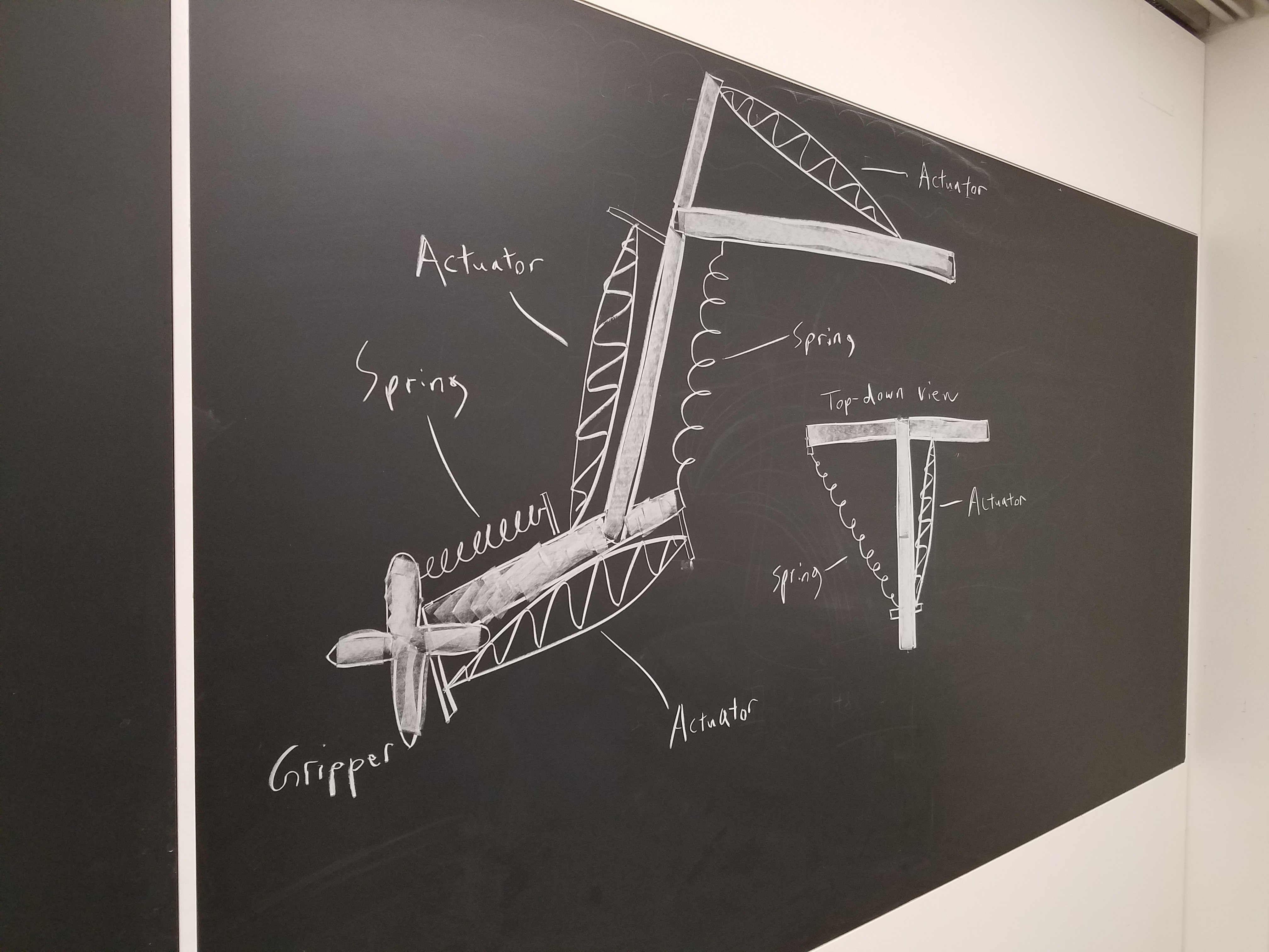
See session 1 for more details.
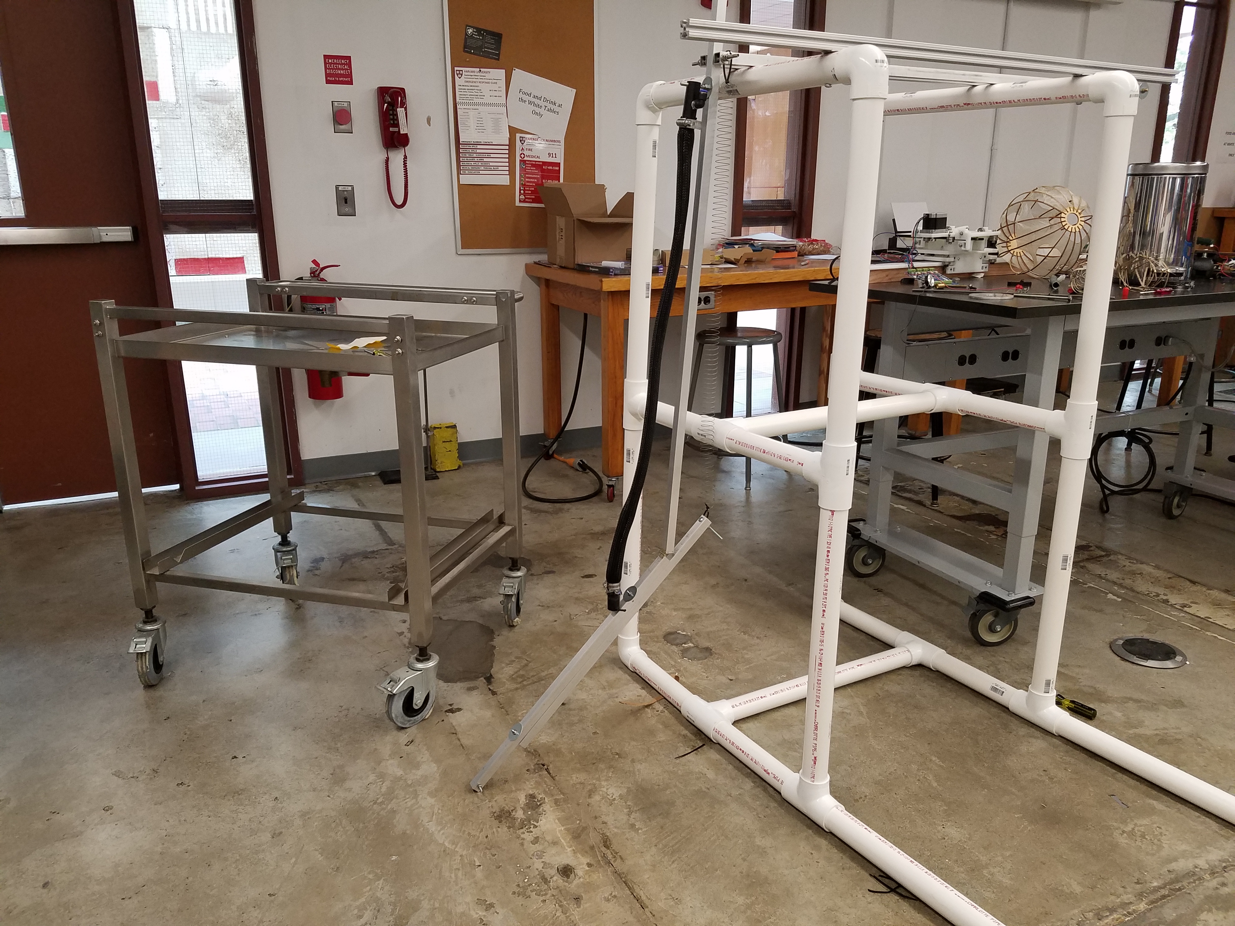
Creating a PVC Stand for my Robot
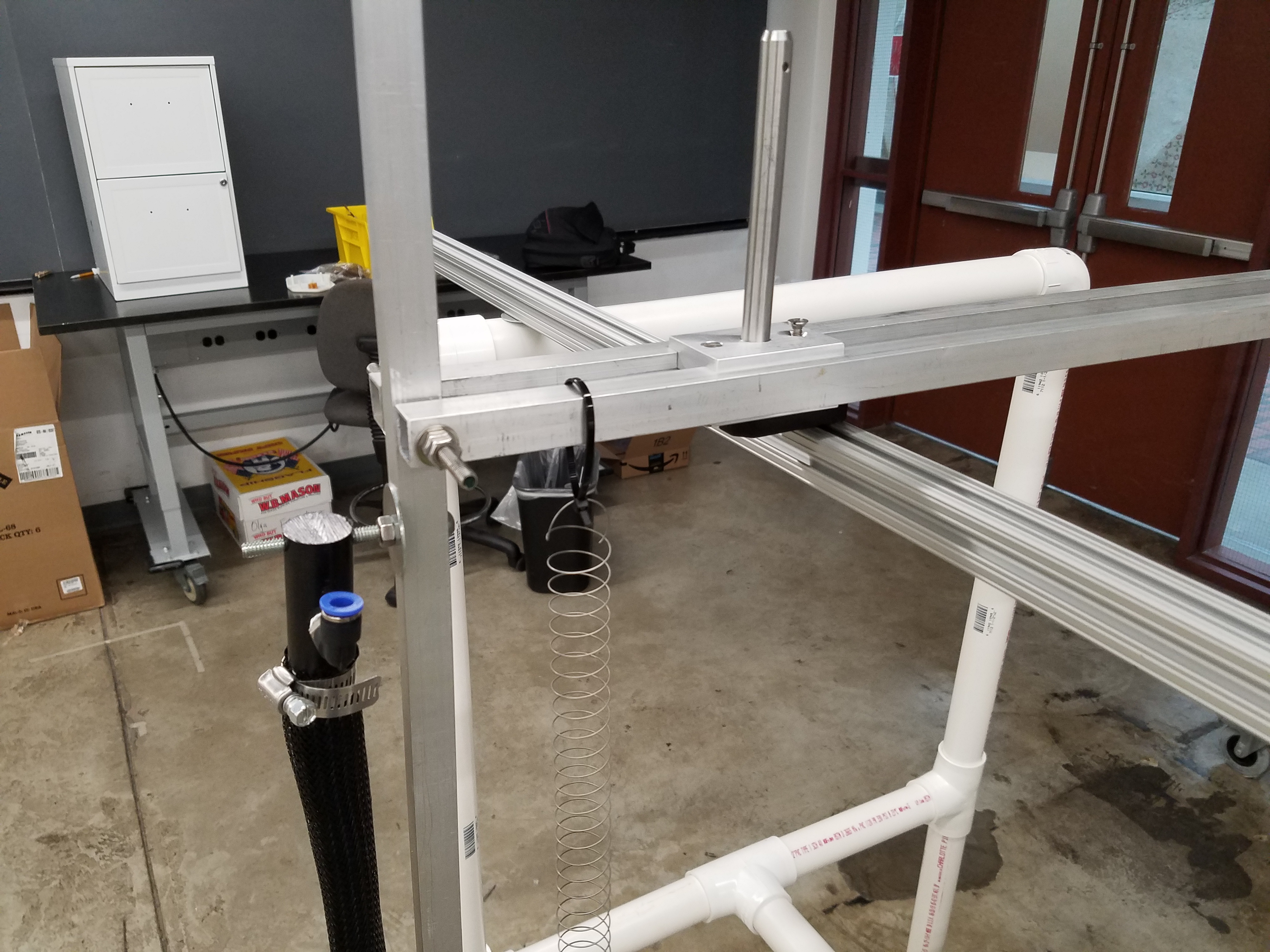
Since I work at the SEAS Instructional Machine Shop, I have access to a very nice tool known as a horizontal saw. It is ideal for cutting round objects (which a standard band saw has trouble cutting), and it can even be automated. I used the horizontal saw to cut some PVC which I used to make a quick and dirty stand for my pneumatic robot arm, so I don’t have to waste time finding one that’s high enough or build my own out of wood.
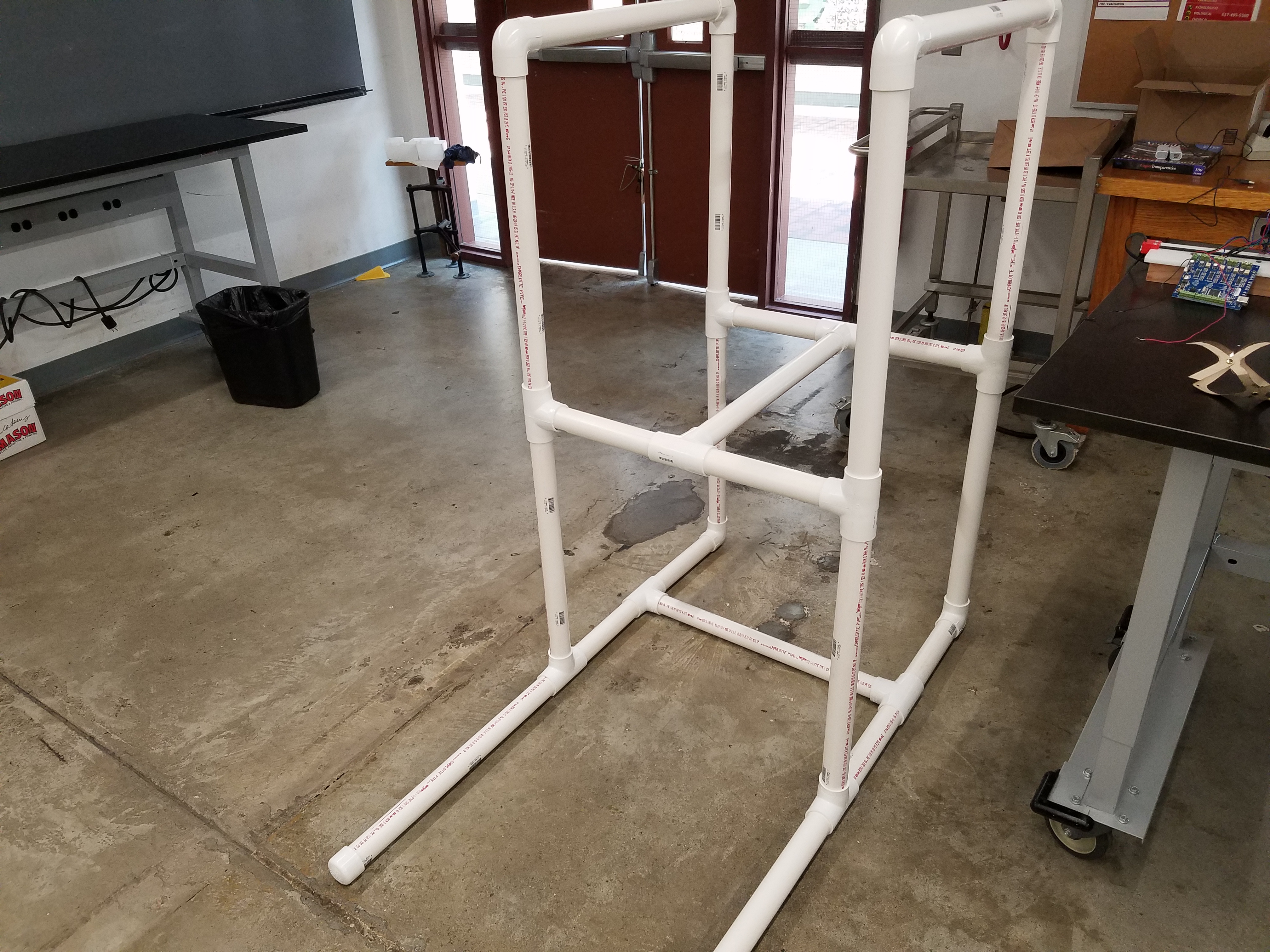
I then attached an 80/20 slotted aluminum rod to the top of the stand. This is where I will pivot my robot arm off of. In order to do this, I drilled two holes in two adjacent pipes, and then cut (using the hack saw) and filed down some long screws with a belt sander, so they could fit into a nut just inside the 80/20 slot.
See session 2 for more details and videos.
Creating a Soft Gripper
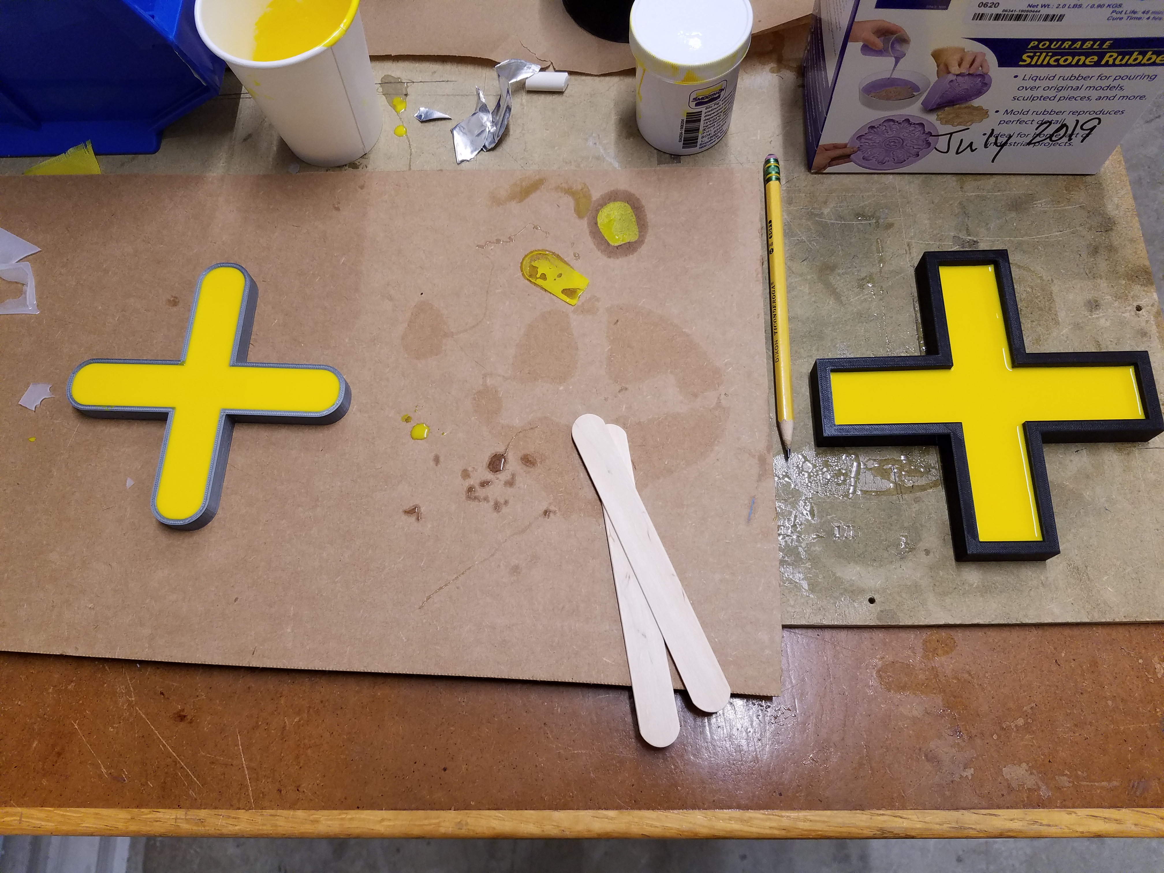
I wanted to make my soft grippers more attractive-looking, so I used something called Silc Pig to dye the Ecoflex bight yellow. I bought the Silc Pig from Reynolds Advanced Materials in Brighton, and according to the staff there, it works best when you mix it in with part B of the Ecoflex before you combine both parts.
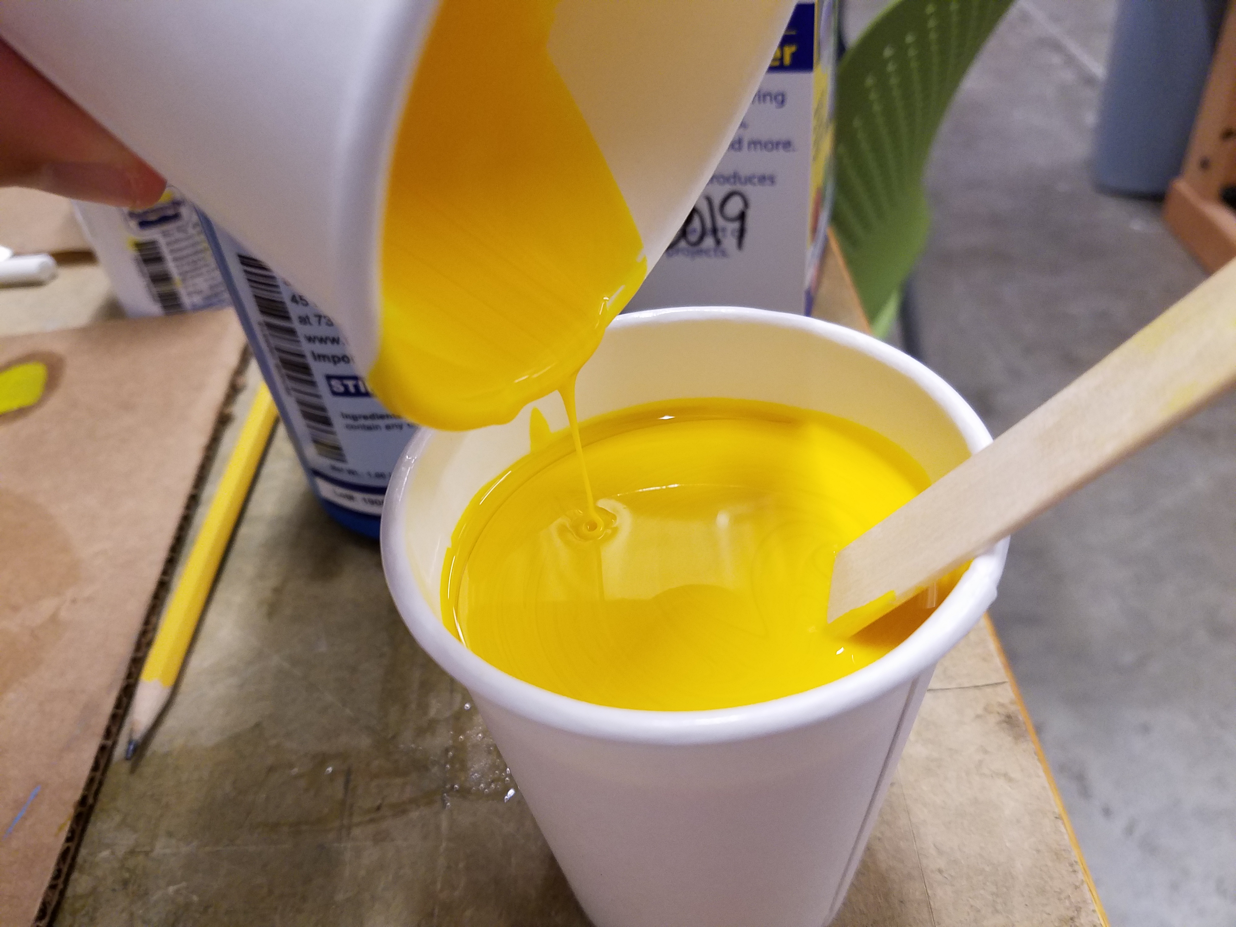
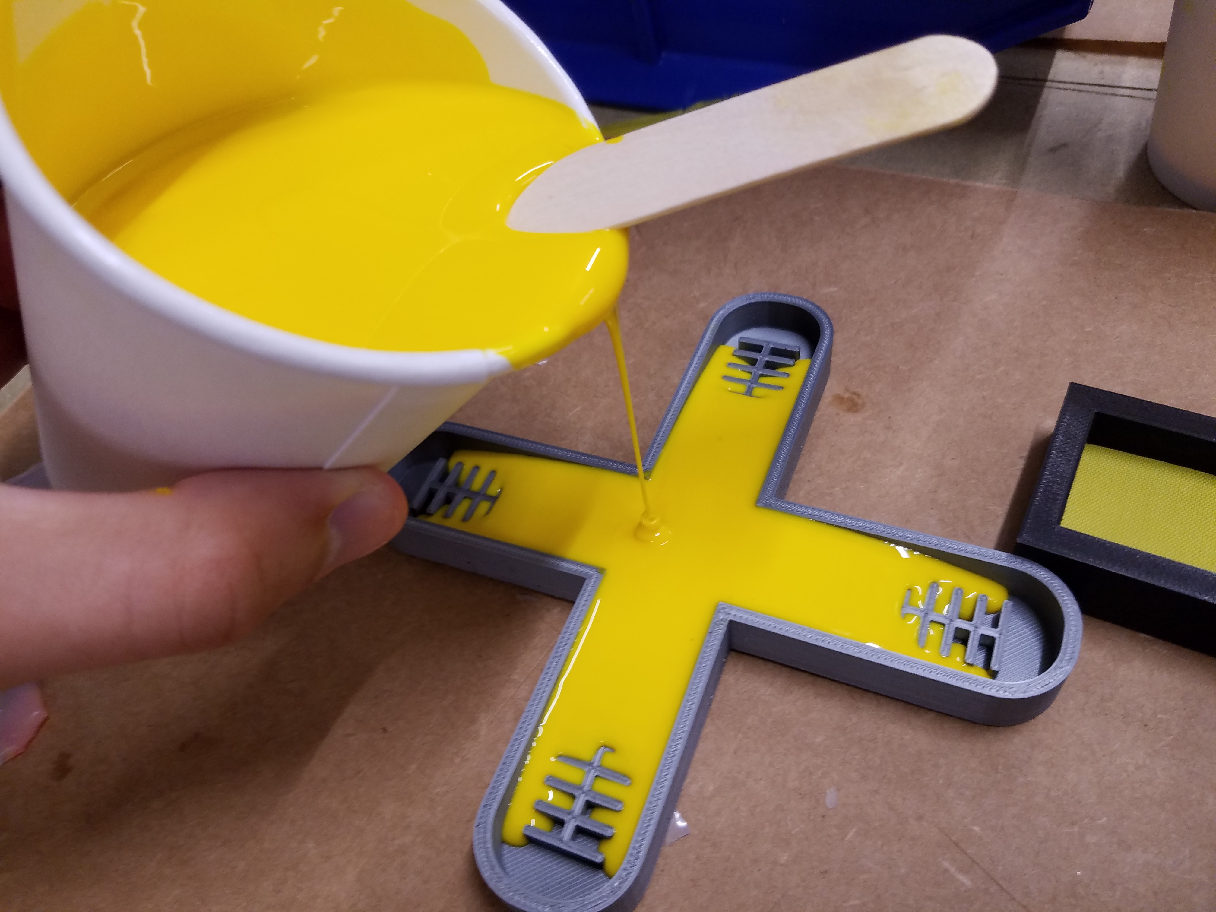
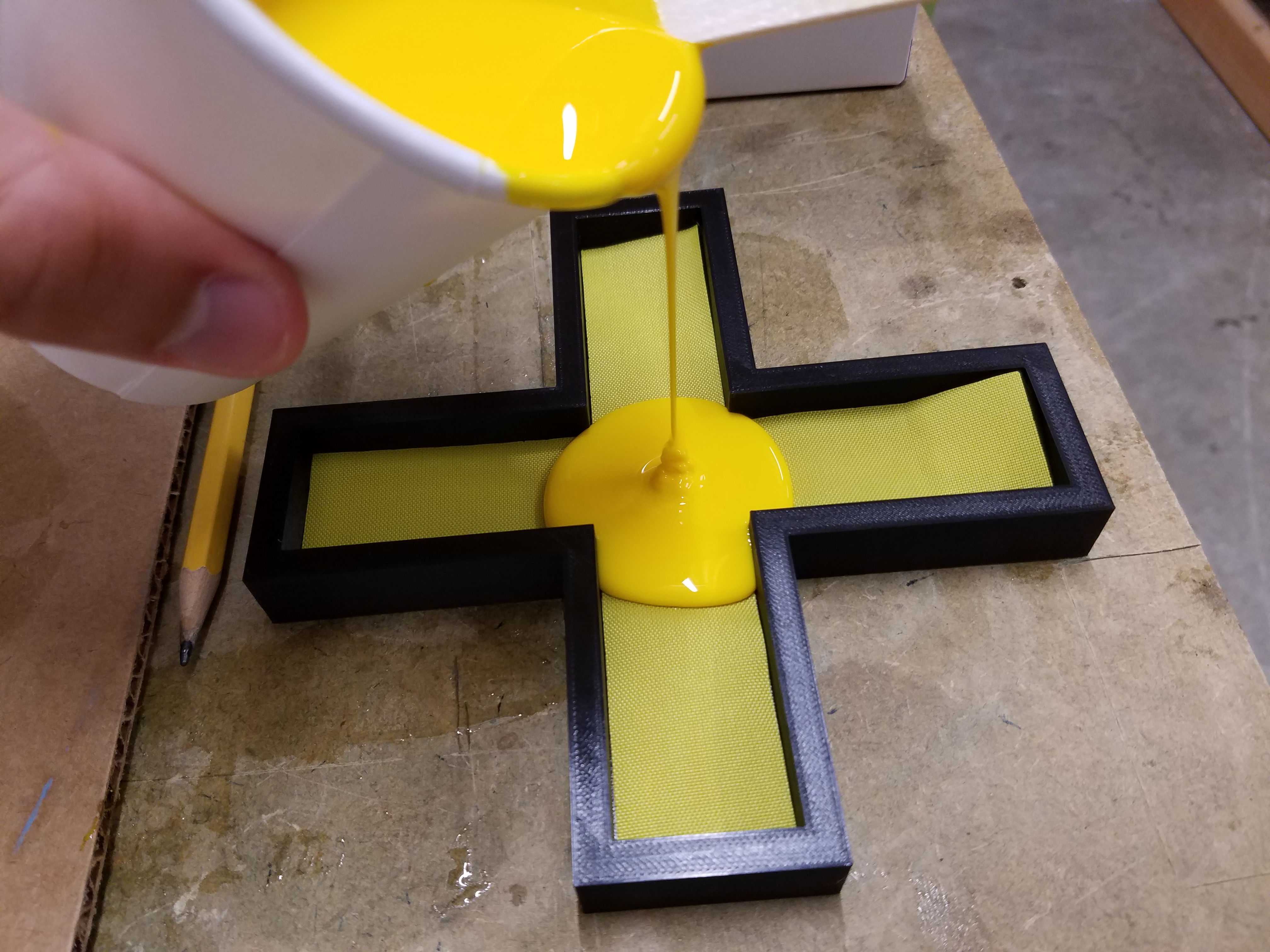
For the fabric, I laser cut some yellow nylon I found in the fabric bin. I cut it to the same exact dimensions as the lower half mold I designed in session 6. This fabric fit snugly into the bottom mold. As Nathan put it, precision is one of the benefits of digital fabrication.
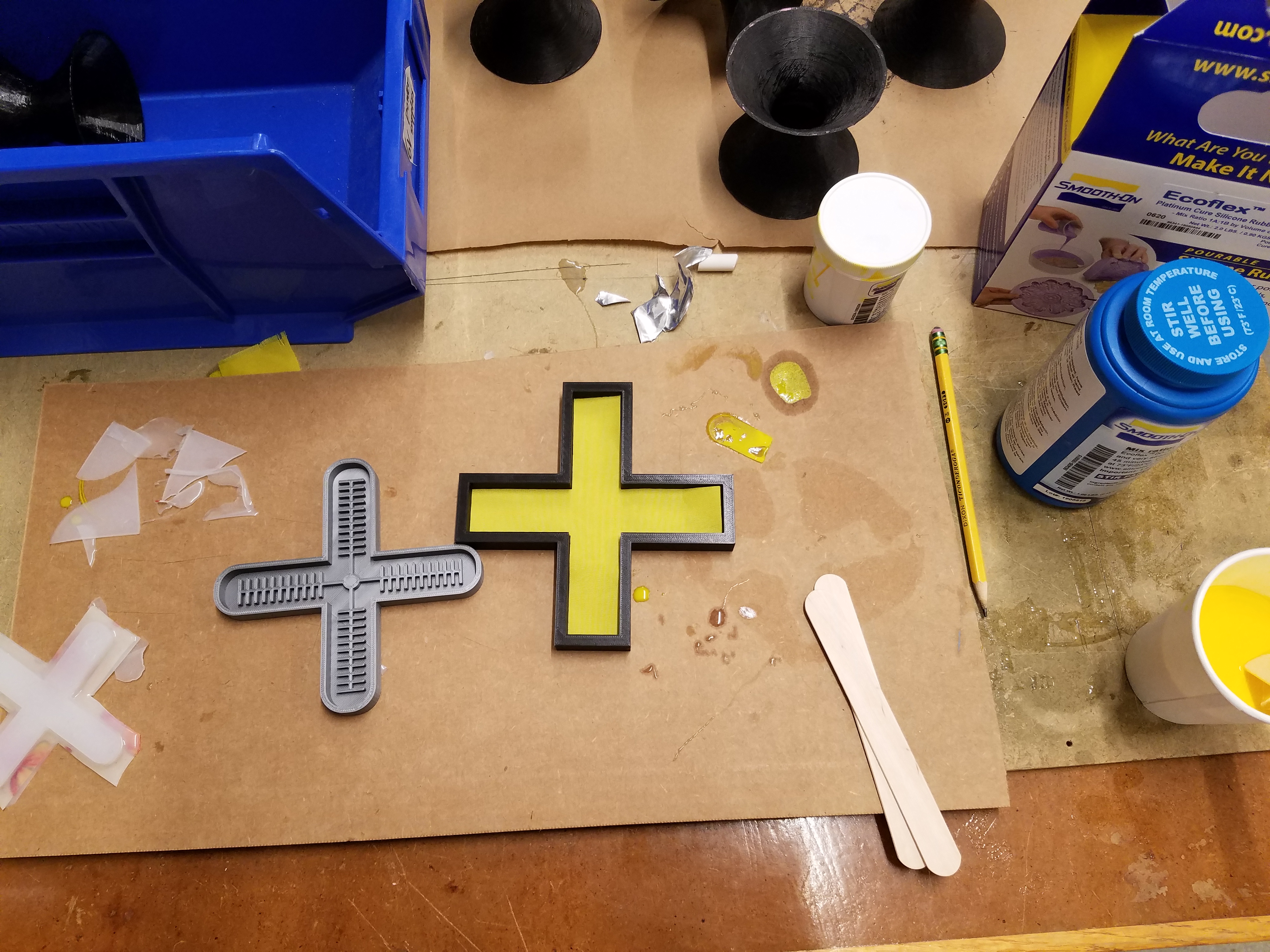
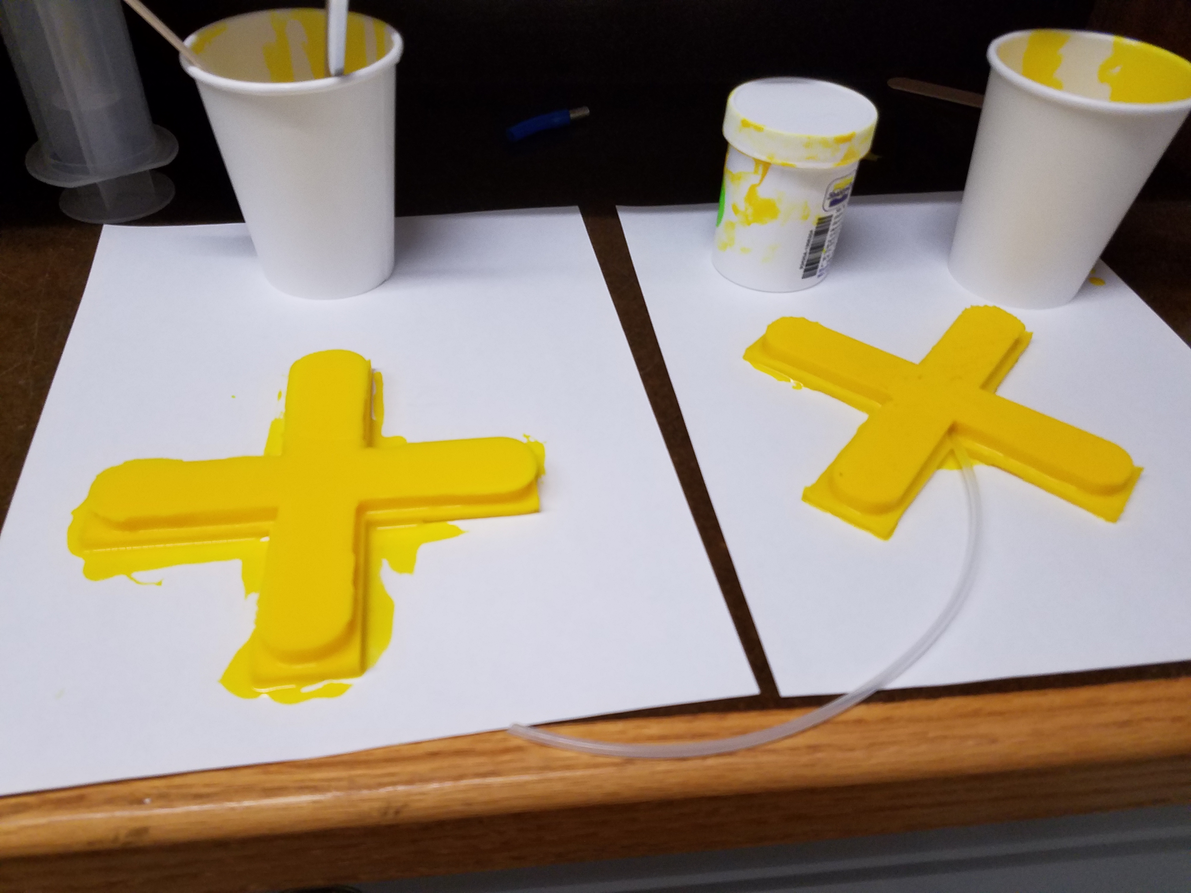
I poured the Silc-Pig-dyed Ecoflex into both this mold and the larger upper half mold from session 6:
These are now left to cure for a while.
See session 10 for more details and videos.
Troubleshooting the Soft Gripper
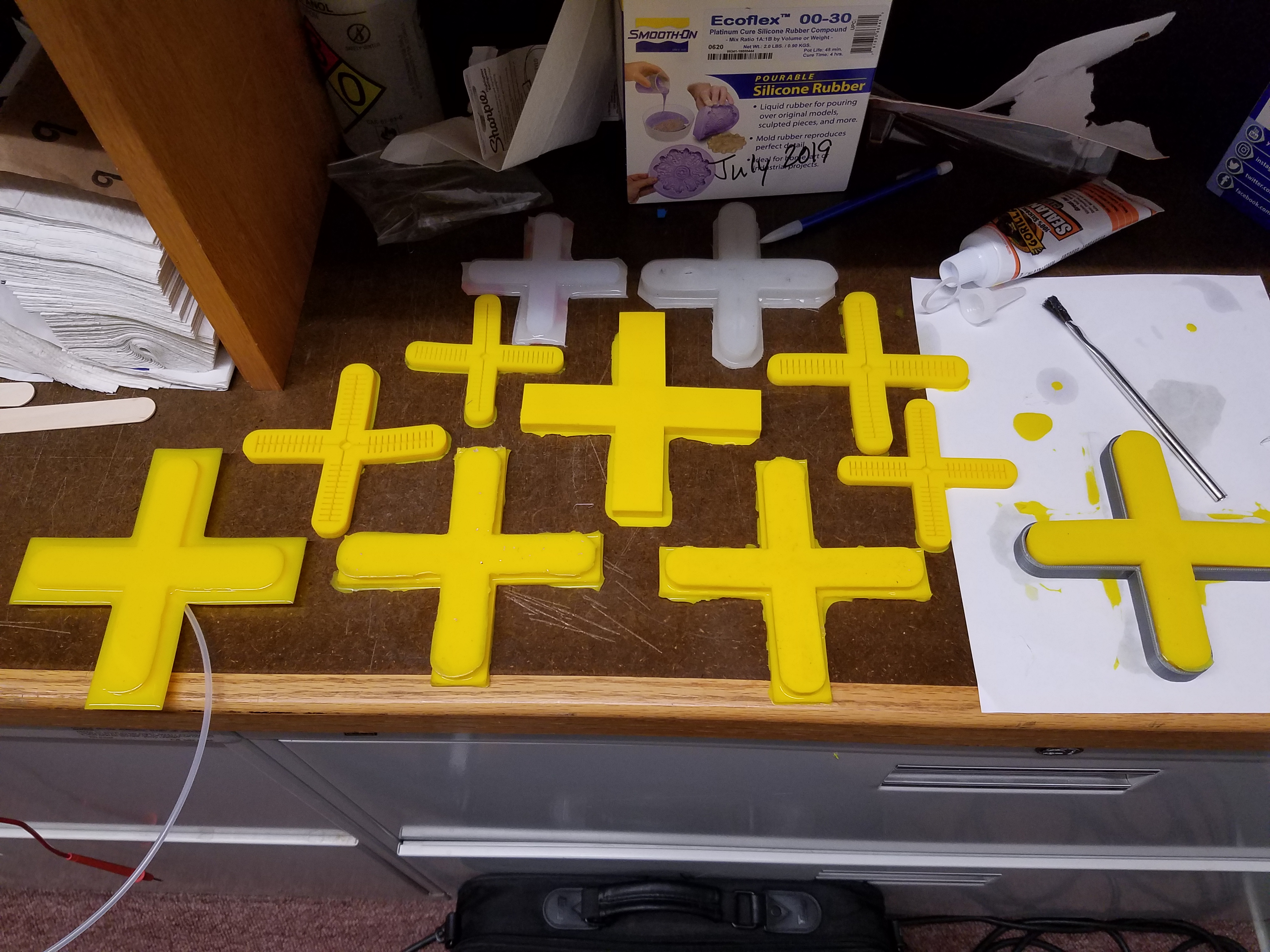
I repeated this process many times, and I ran into many problems along the way. The first time I tried to make a large gripper, I tried to take an upper half that was already cured and place it on top of a lower half as it was still in the process of curing, and it was my hope that they would bond without needing to use Ecoflex as glue. However, this just resulted in the upper half sinking to the bottom of the lower half, creating a soft gripper where both halves are completely merged. The nylon also turned out to be not so great at bonding to the silicone, and actually floated to the top of the curing Ecoflex while it was still viscous. In future attempts, I would use double sided tape to prevent this.
The next time I tried to make a large gripper, I let both halves fully cure, and tried to use Ecoflex as a glue again.
I tried this with two soft grippers, but they both ran into the same problem. Even though I tried my best, the glue did not spread evenly, and there were uneven air pockets within the gripper as a result. Whenever air was pumped into the grippers, the air would immediately try to fill these voids, since currents want to take the path of least resistance. When the air filled these pockets, that particular area would expand rapidly and eventually pop. I could fix these ruptures with silicone Gorilla Glue, but this would only cause air to gravitate towards another pocket and the process would repeat. Fixing these grippers with Gorilla Glue would be tedious and would take forever.
Finally, after both halves were cured, I took the bottom half, flipped it over, placed it inside the bottom mold again, and poured in another thin layer of Ecoflex. I then placed the upper half on top, essentially treating the new layer as a perfectly-spread layer of glue. This finally did the trick!
See session 10 for more details.
Programming the Arduino
One of the problems I ran into when testing my elbow configuring was that the solenoid valve I used was not strong enough to withhold all of the air pressure coming from the tank. As a result, a little bit of air leaked through when no buttons were pressed, causing the arm to slowly rise without a given command to rise.
To fix this, I will have a “master solenoid valve,” on top of the solenoid valves for each joint of the robot, and I will create an Arduino program that will only open the master valve when one of the joint valves is opened (i.e. when I want the robot to move). I tested two solenoid valves in series, and found that two of them are sufficient at withholding the air pressure from the tank.
The program is as follows:
// The purpose of this program is to activate valve 5
// when any combination of the first four valves are activated

// unchanging constants
const int valveOne = 2;
const int valveTwo = 3;
const int valveThree = 4;
const int valveFour = 5;
const int valveFive = 6;

// variables
int valveOneState = 0;
int valveTwoState = 0;
int valveThreeState = 0;
int valveFourState = 0;

void setup() {

  // initialize valves 1-4 as inputs:
  pinMode(valveOne, INPUT);
  pinMode(valveTwo, INPUT);
  pinMode(valveThree, INPUT);
  pinMode(valveFour, INPUT);

  // initialize valve 5 as an output:
  pinMode(valveFive, OUTPUT);

}

void loop() {

  // find the state of valves 1-4:
  valveOneState = digitalRead(valveOne);
  valveTwoState = digitalRead(valveTwo);
  valveThreeState = digitalRead(valveThree);
  valveFourState = digitalRead(valveFour);

  // if ALL valves 1-4 are closed, also close valve 5
  if (valveOneState == LOW && valveTwoState == LOW && valveThreeState == LOW && valveFourState == LOW) {

    digitalWrite(valveFive, LOW);

  } else { // if ANY of valves 1-4 are activated, open valve 5

    digitalWrite(valveFive, HIGH);

  }

}
See session 11 for more details.
Machining some Robot Parts
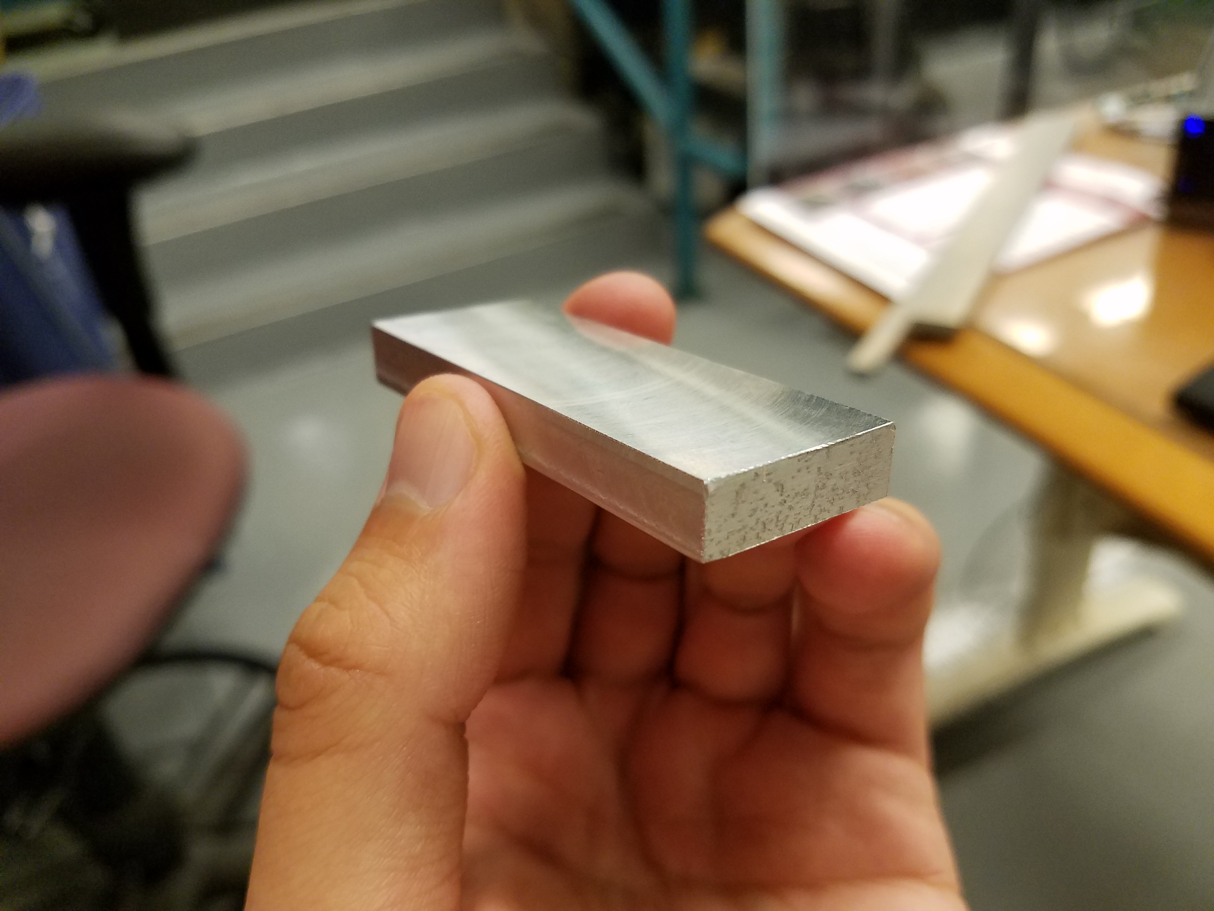
Instead of 3D printing the clamping parts I needed in session 6, I decided to machine them myself at the SEAS Instructional Machine Shop. The first step to machining parts is to determine the dimensions of your pieces, and then finding and cutting the necessary material. I decided to use aluminum, fitting with the rest of my robot.
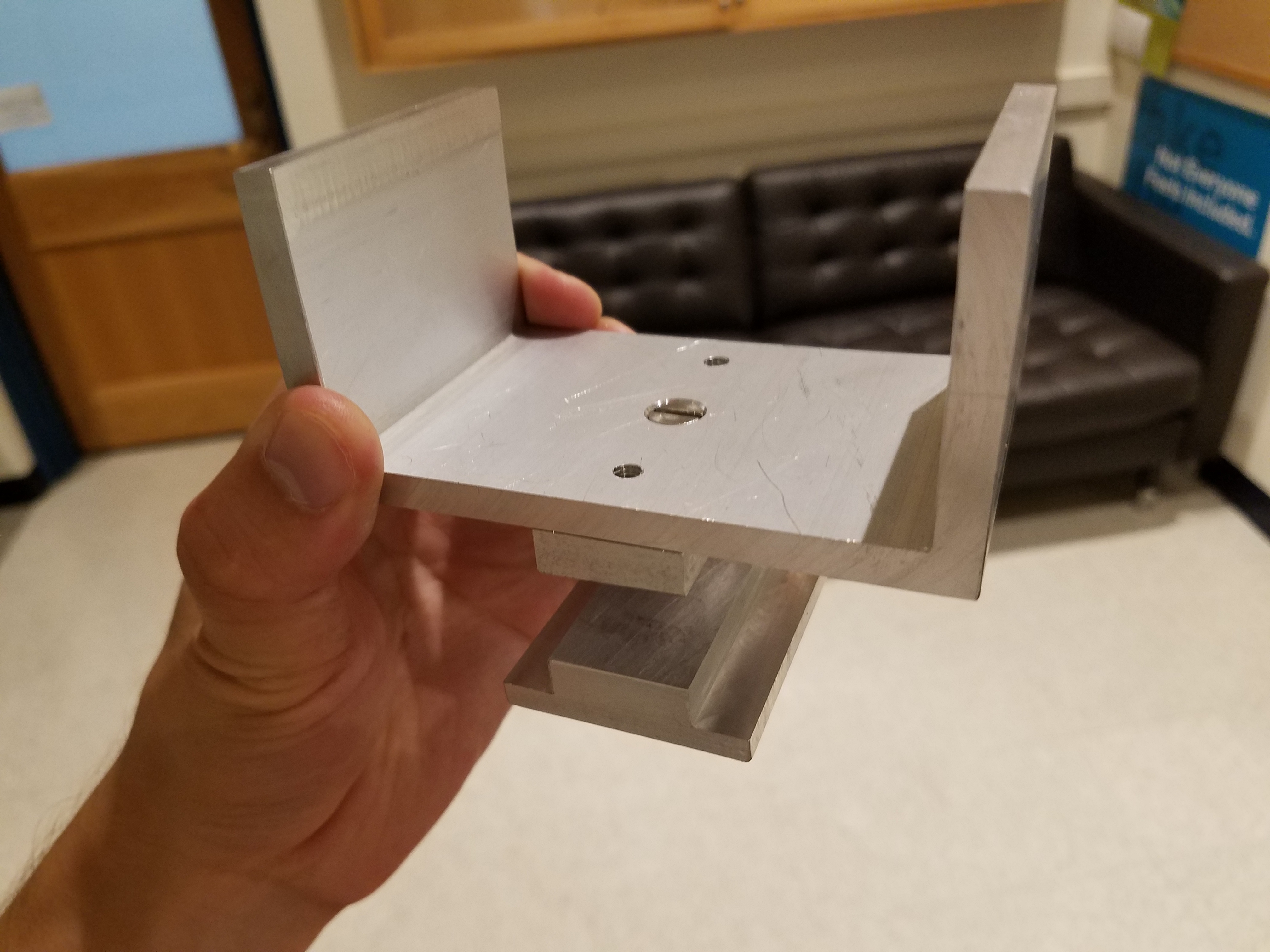
After cutting a rough aluminum bar, I used the grinder to deburr the object. I then precisely machined it using a milling machine to get this nice-looking finished bar:
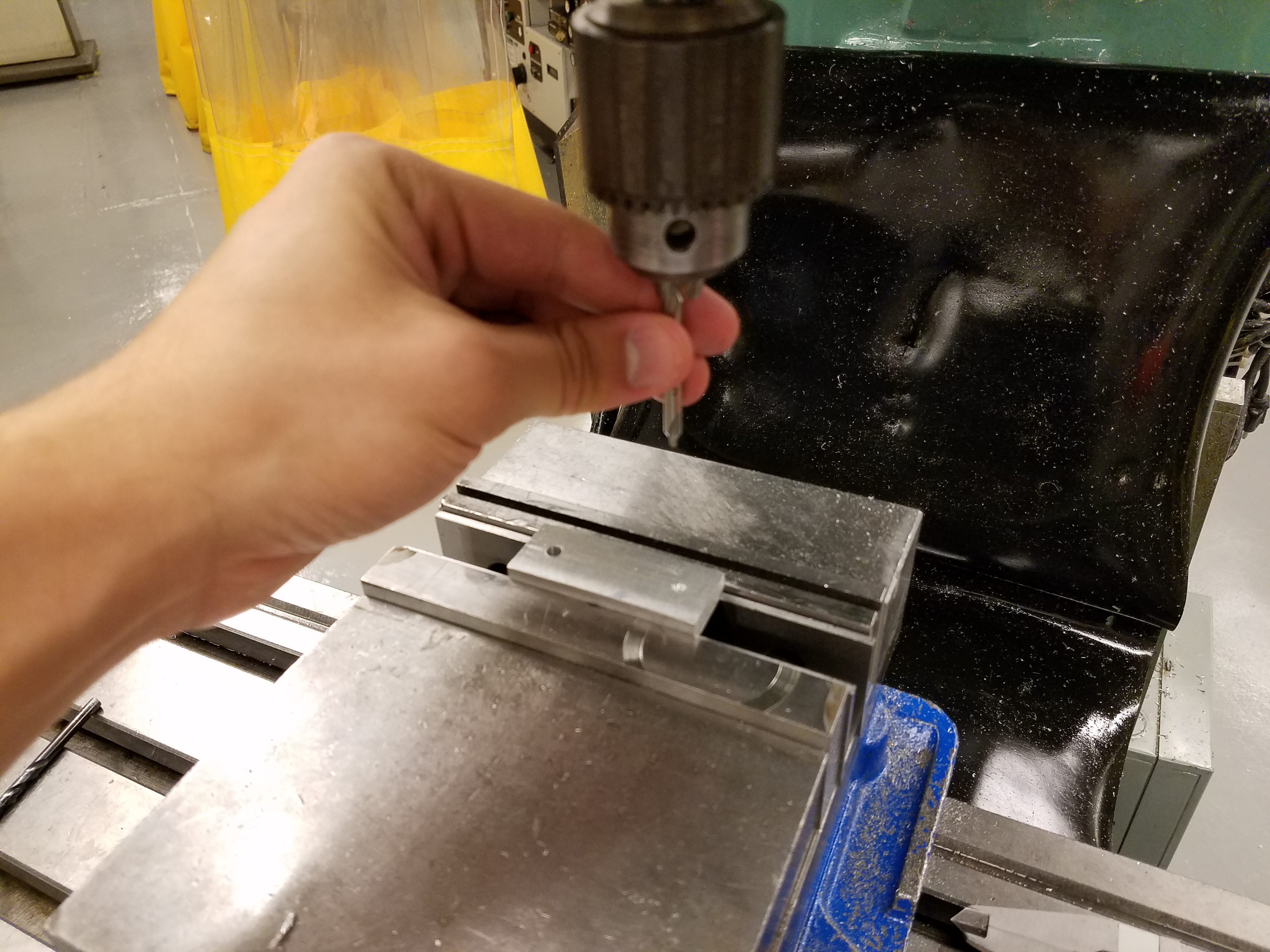
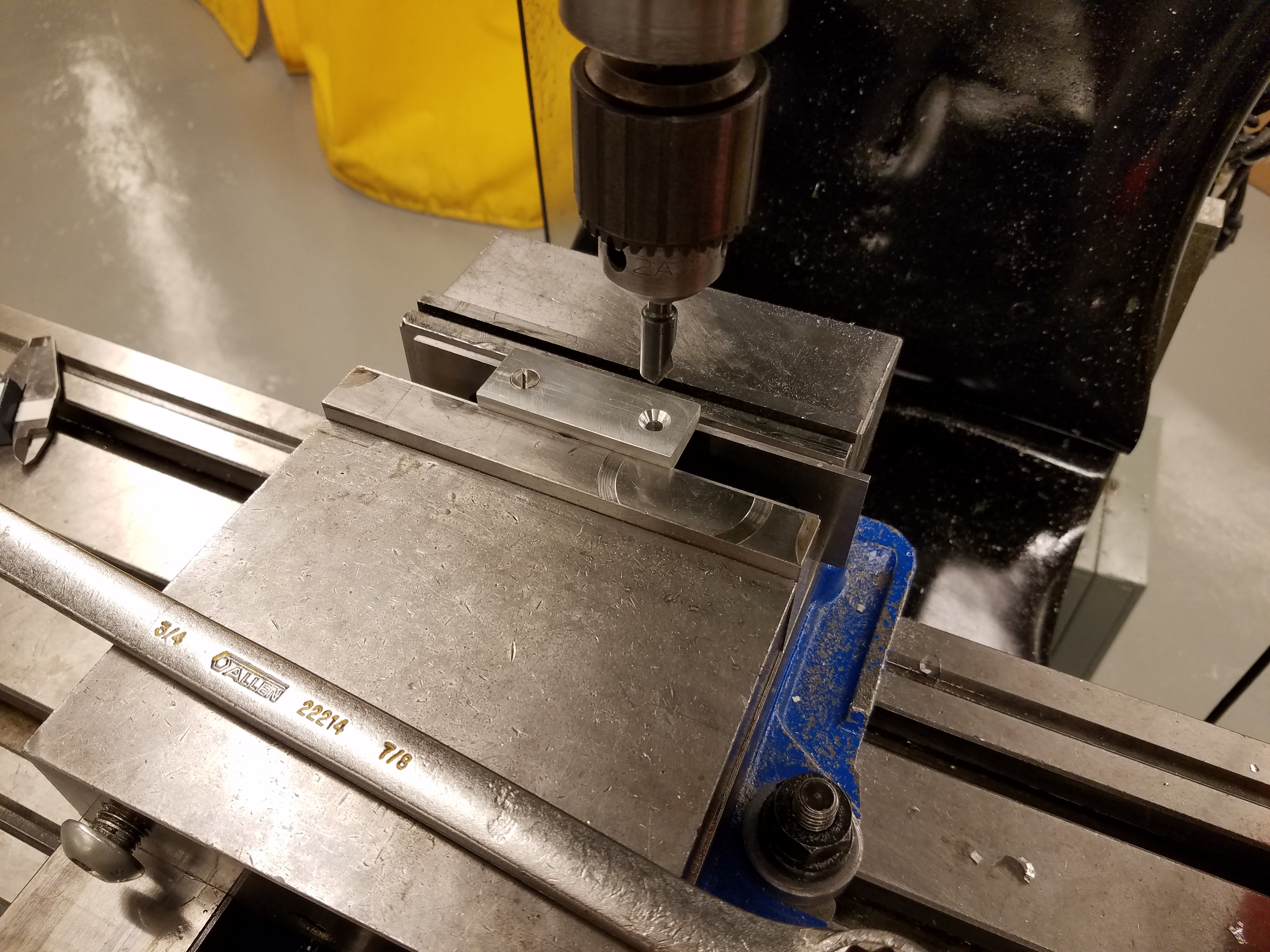
The next step was to drill two holes in the center line of the bar, so I can screw this piece onto a larger U-shaped piece, which I will use as a bracket for my pneumatic cylinder. Before drilling a hole with the milling machine, it is important to use a center drill to create a groove where you want the hole to be, which guides in the drill you actually want to use. This is how machinists are able to get really precise holes even when using large drills.
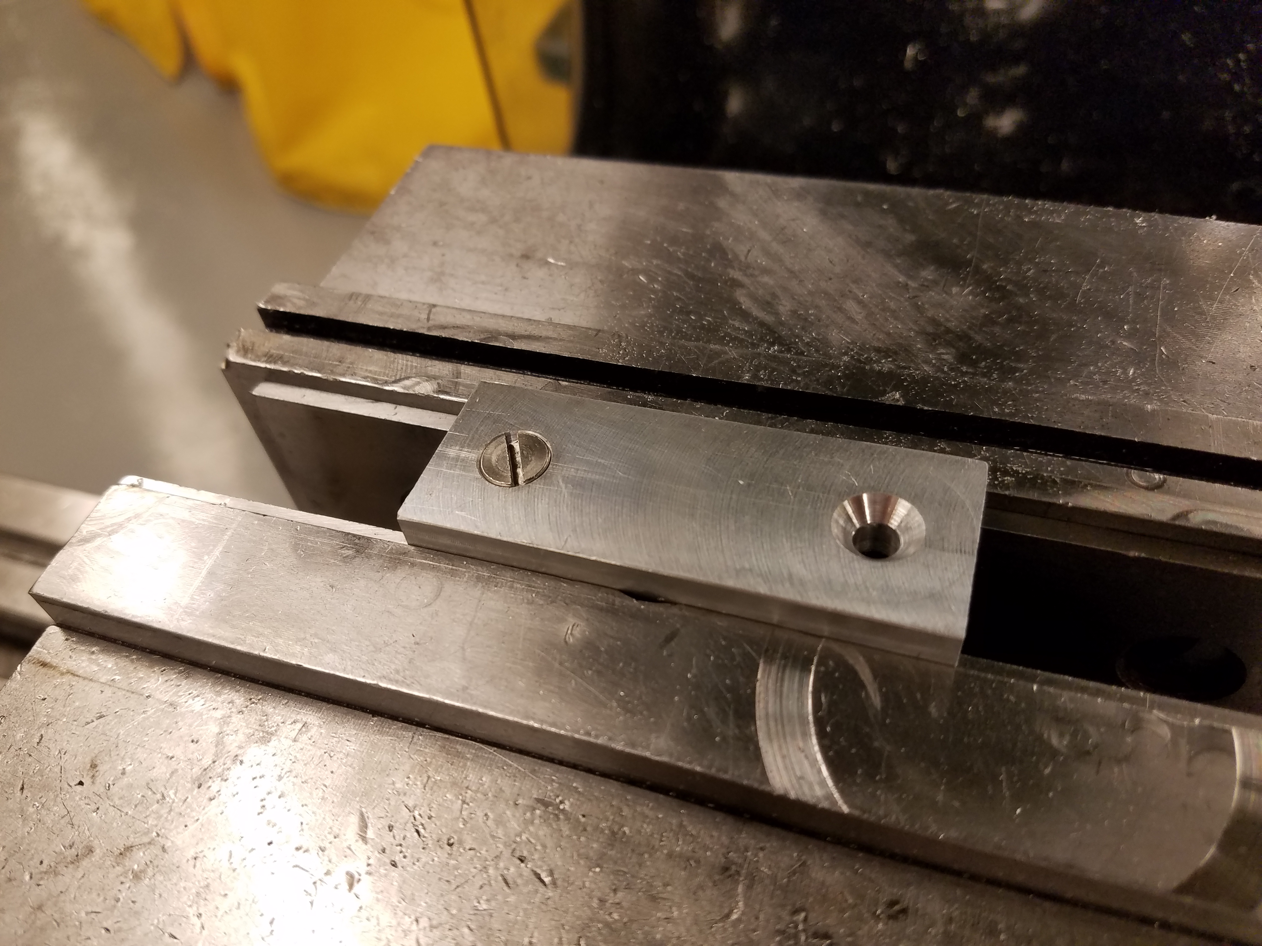
After the holes are drilled, I deburr the rim of the holes using a handheld deburring tool. Now, its time to use a countersink drill on the two holes. This creates a funnel-shaped opening that allows the fitting of a flathead screw that is completely flush with the surface of the part.
My bar is finished, and now its time to attach it to my U-shaped piece:
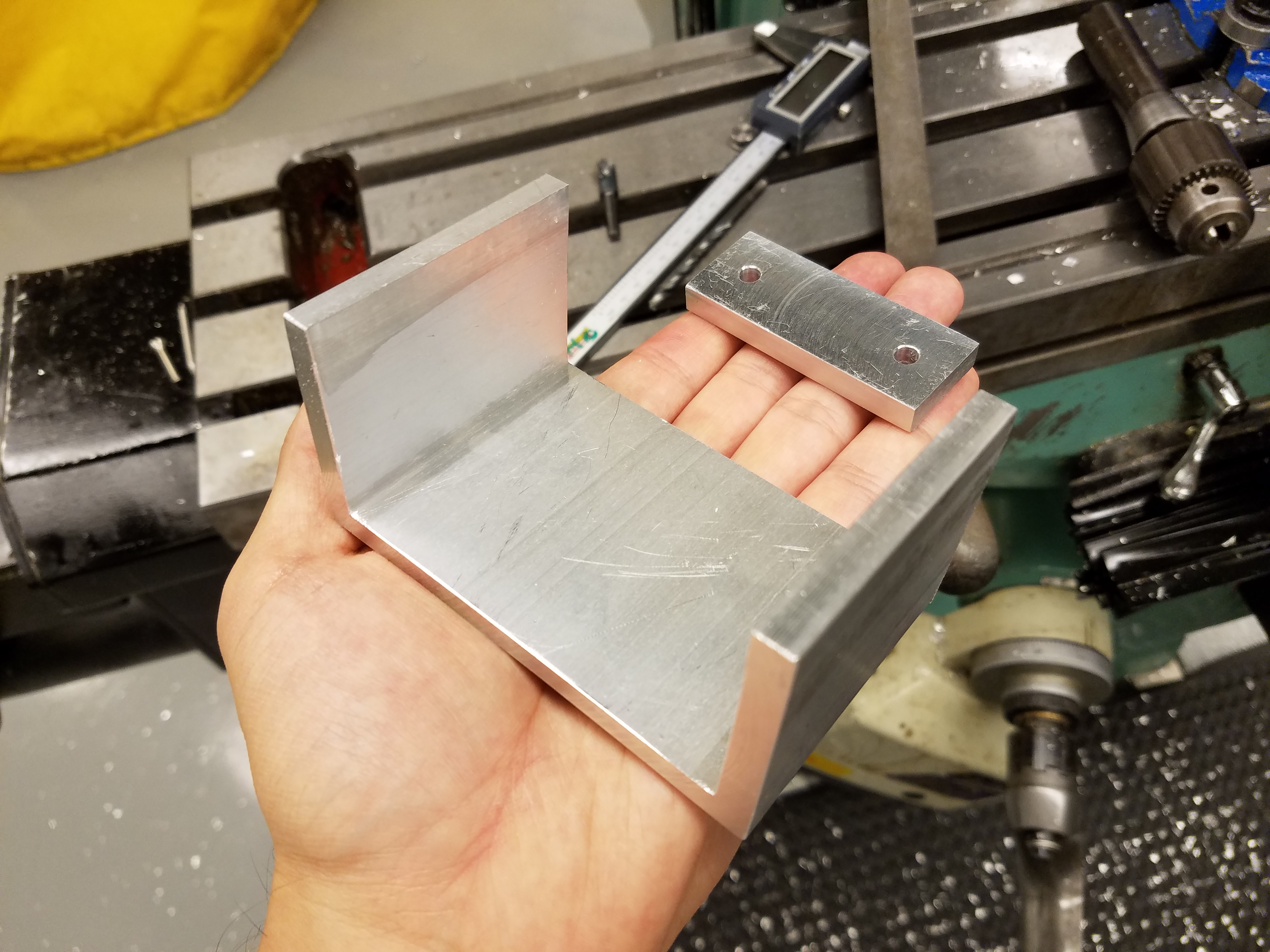
The U-shaped piece was originally a rectangular-shaped tube with the top removed using an endmill on the milling machine. To fix my bar to this piece, I use a very similar process to drill two holes, but this time I use a smaller drill diameter, so I can tap the holes and allow the flatheads to screw in without the need for nuts and washers.
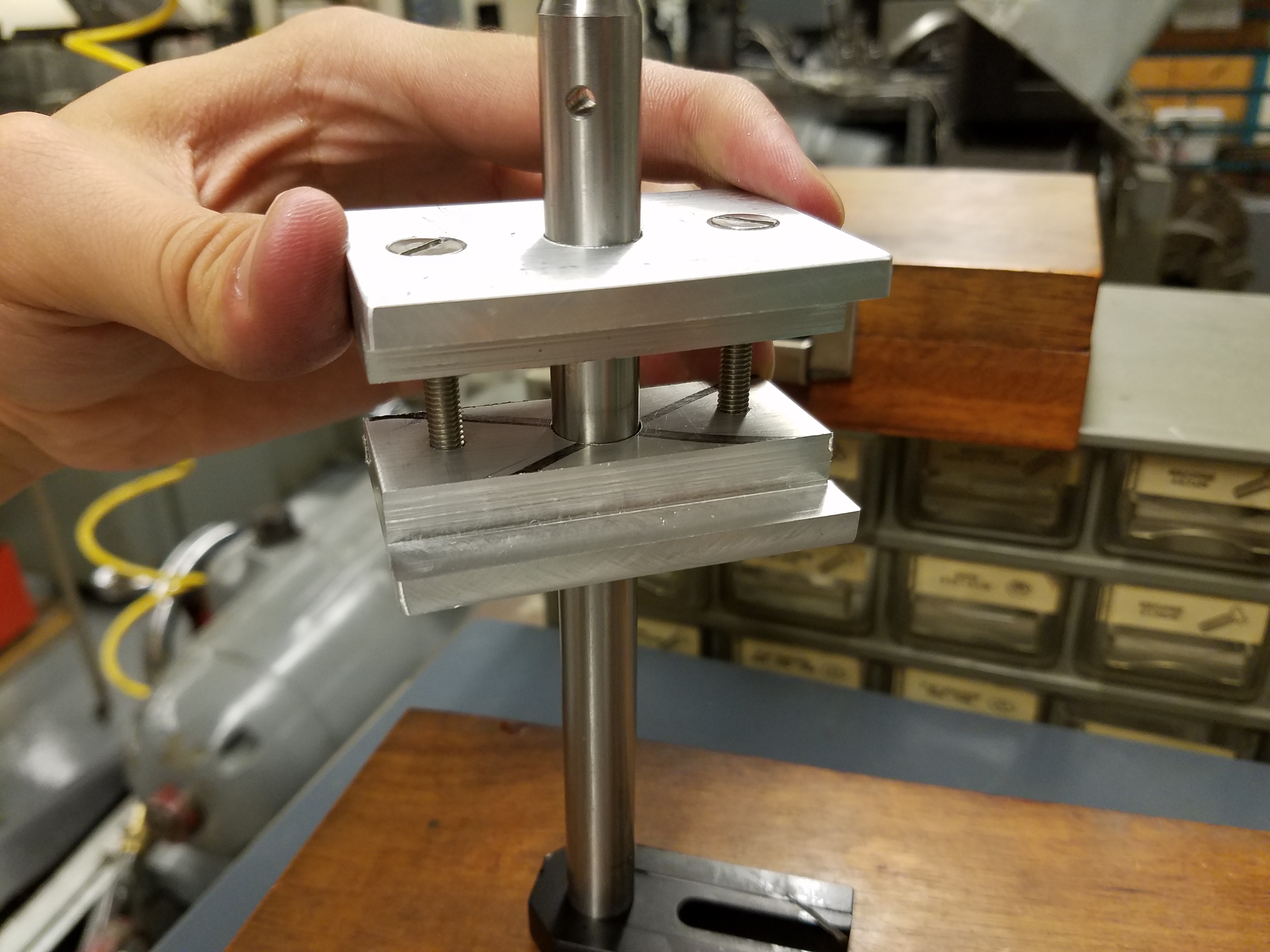
I then cut three identical t-shaped bars using an endmill and deburred them with a grinder. By drilling a center hole in one of these, I was able to finish my clamp for the pneumatic cylinder by drilling a smaller and tapped hole in the U-shaped piece:
I took the two remaining t-shaped bars and used a similar process for two holes at the ends, and a large hole in the center which fits snugly around the rod of a Thor Labs clamp. This is how my robot will piviot about its shoulder.
See session 11 for more details.
Creating the Joints
The elbow is simply a hinge I got from Home Depot.
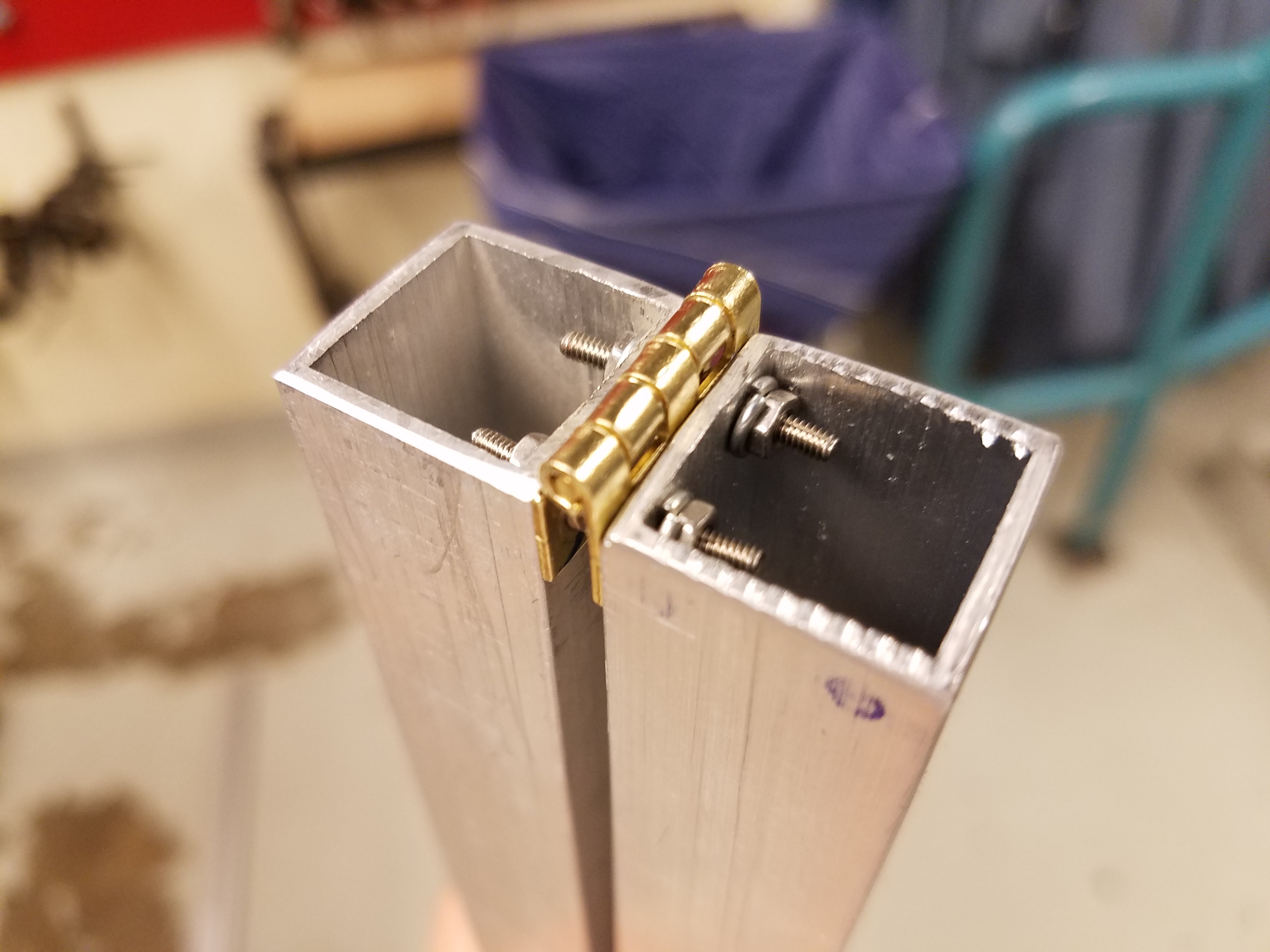
The hinge is not very sturdy, so in order to prevent dislocation, I braced it with two large washers that are simply tied around the elbow using zip ties. This will do for now until I implement a better elbow into the robot. The elbow still works fine even with the braces:
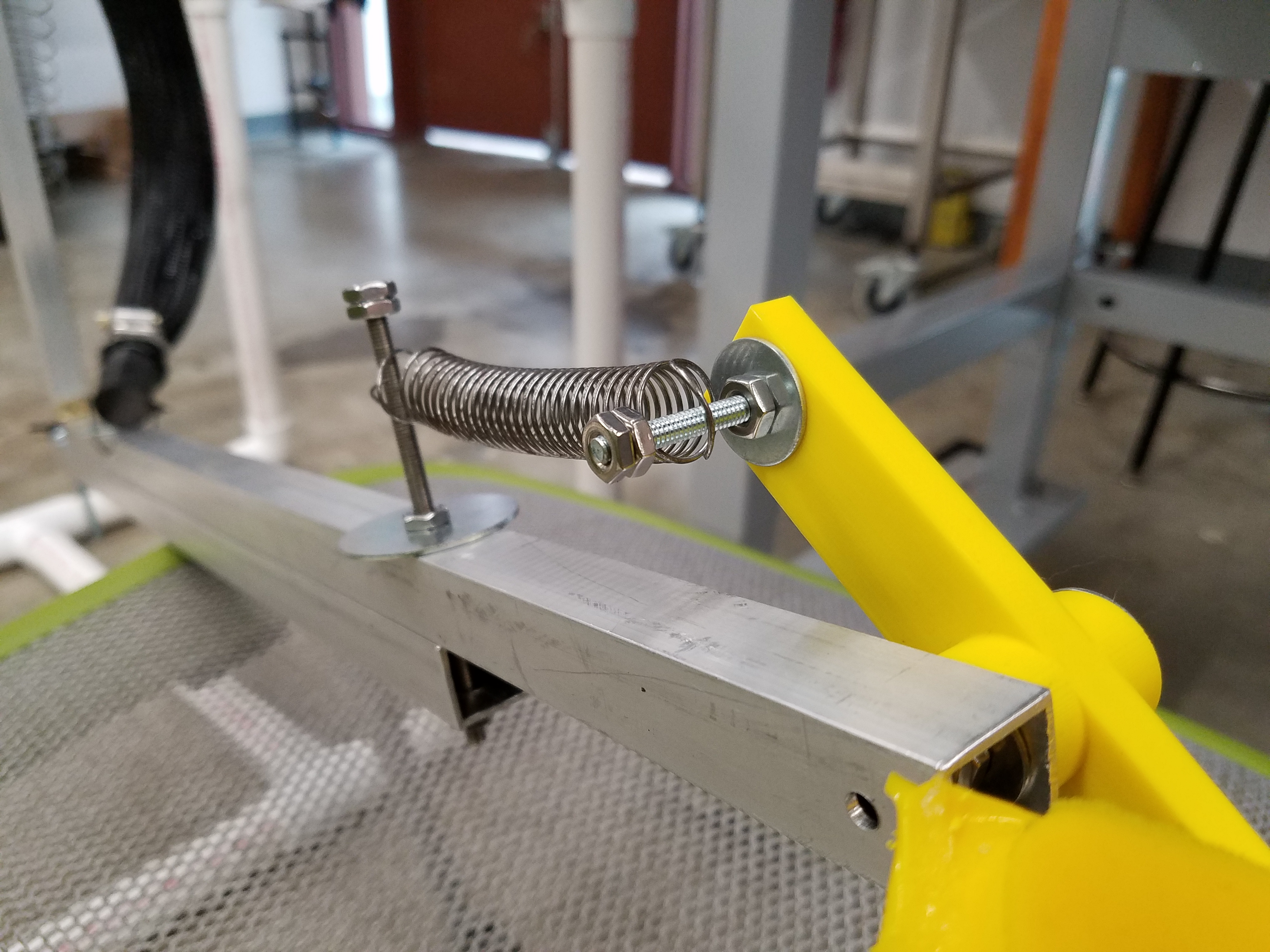
The robot pivots about two of the clamps that I machined earlier. Again, this pivot can be adjusted along the track of the robot.
A McKibben actuator will pull the robot one way about this pivot, while a spring will pull it in the opposite direction when the actuator is relaxed.
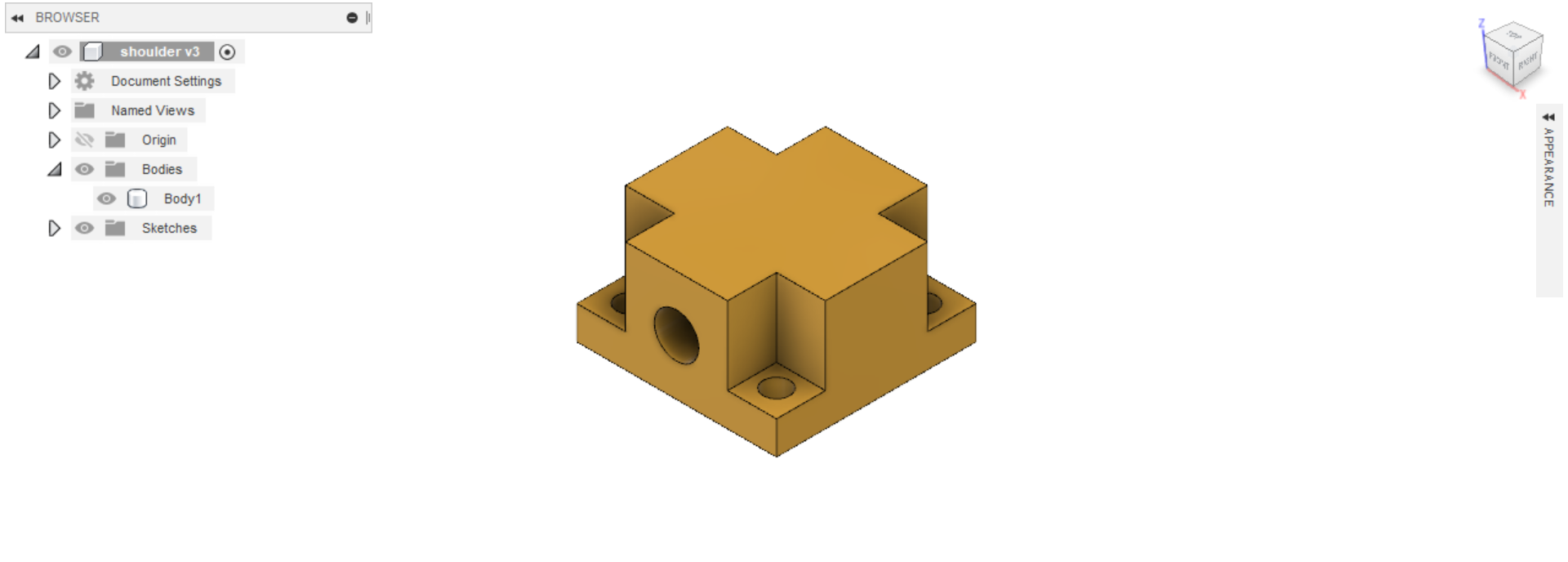
I created the air cylinder holder and wrist out of 100% infill 3D printed PLA (.stl files can be found here and here).
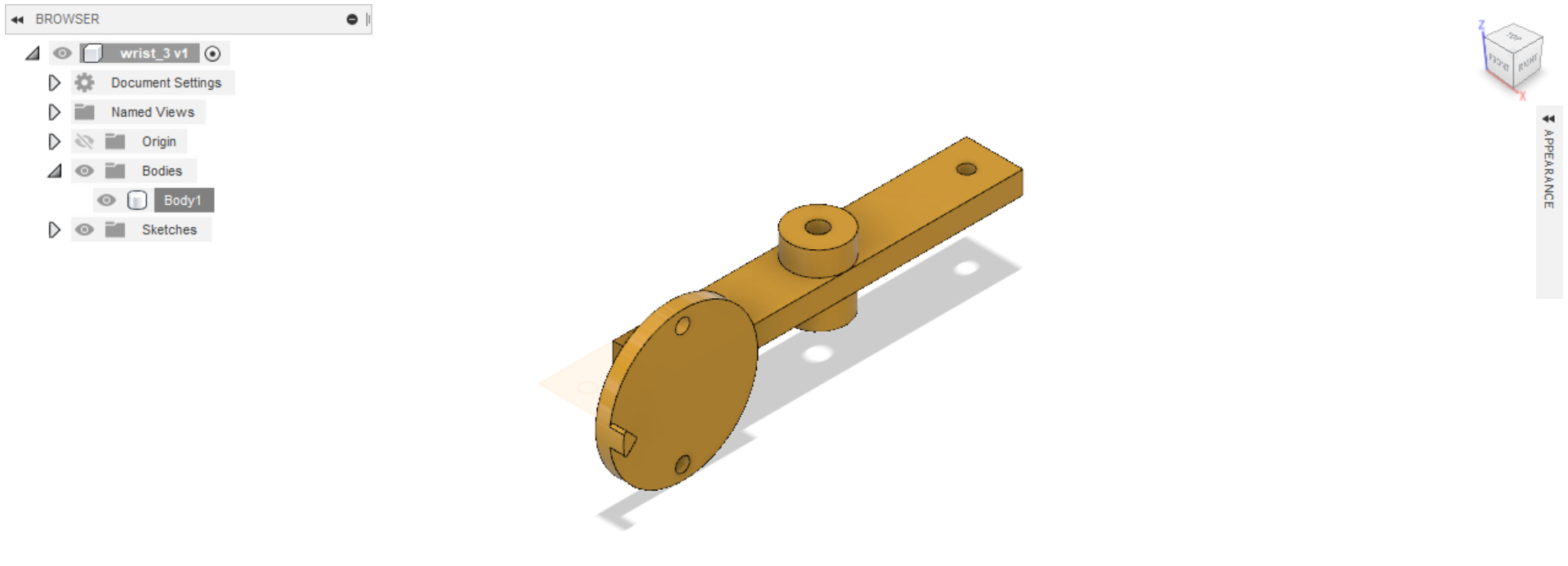
The wrist is designed to snugly hold one of the soft grippers, as well as pivot about a point and can be pulled by either the McKibben actuator or a spring.
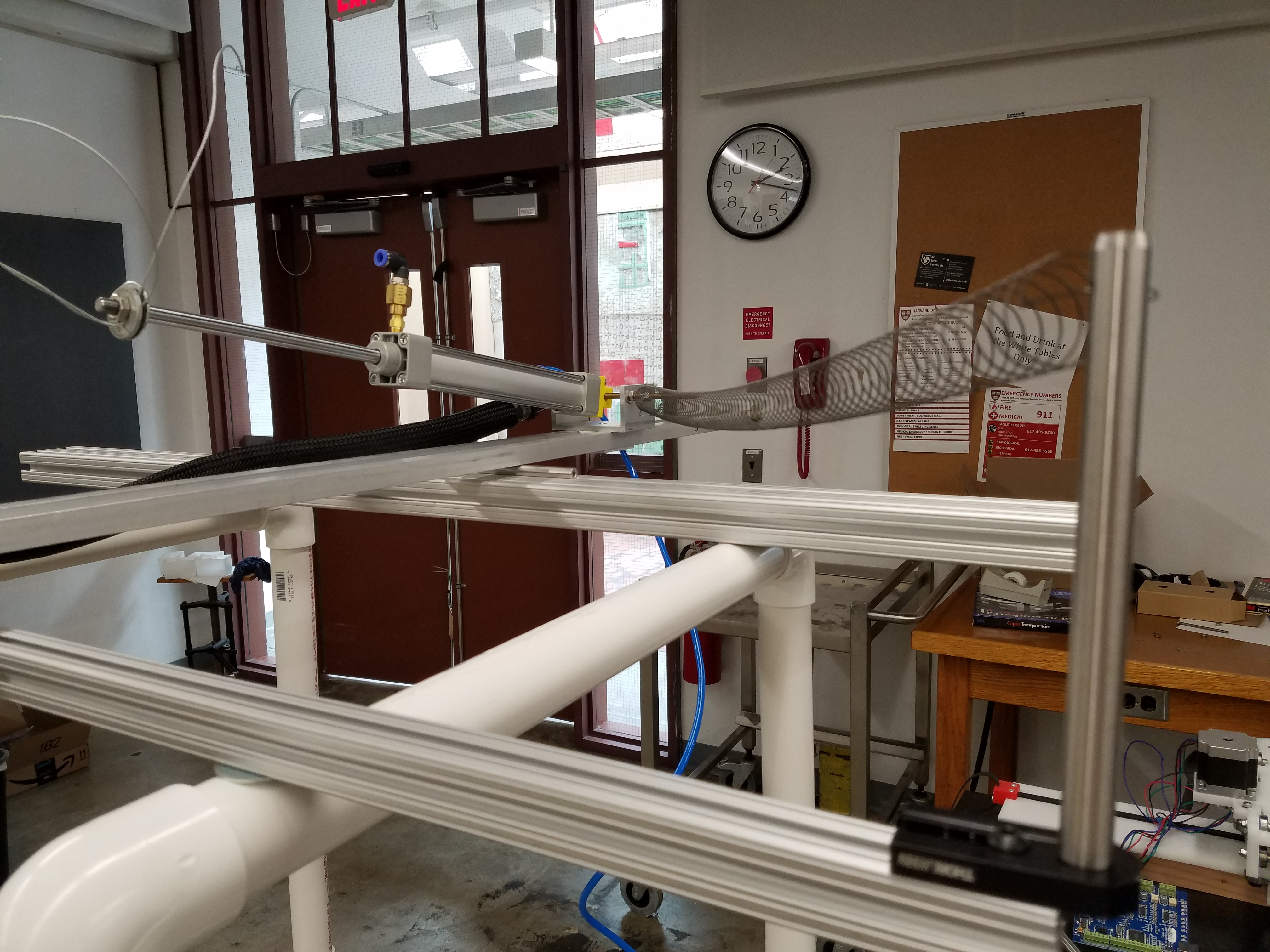
The air cylinder holder is screwed to the air cylinder (obviously), and is connected to the bracket I machined earlier. The bracket can slide up and down the track, and can be clamped in place once the desired location is found. This allows for flexibility and eliminates the need to drill holes.
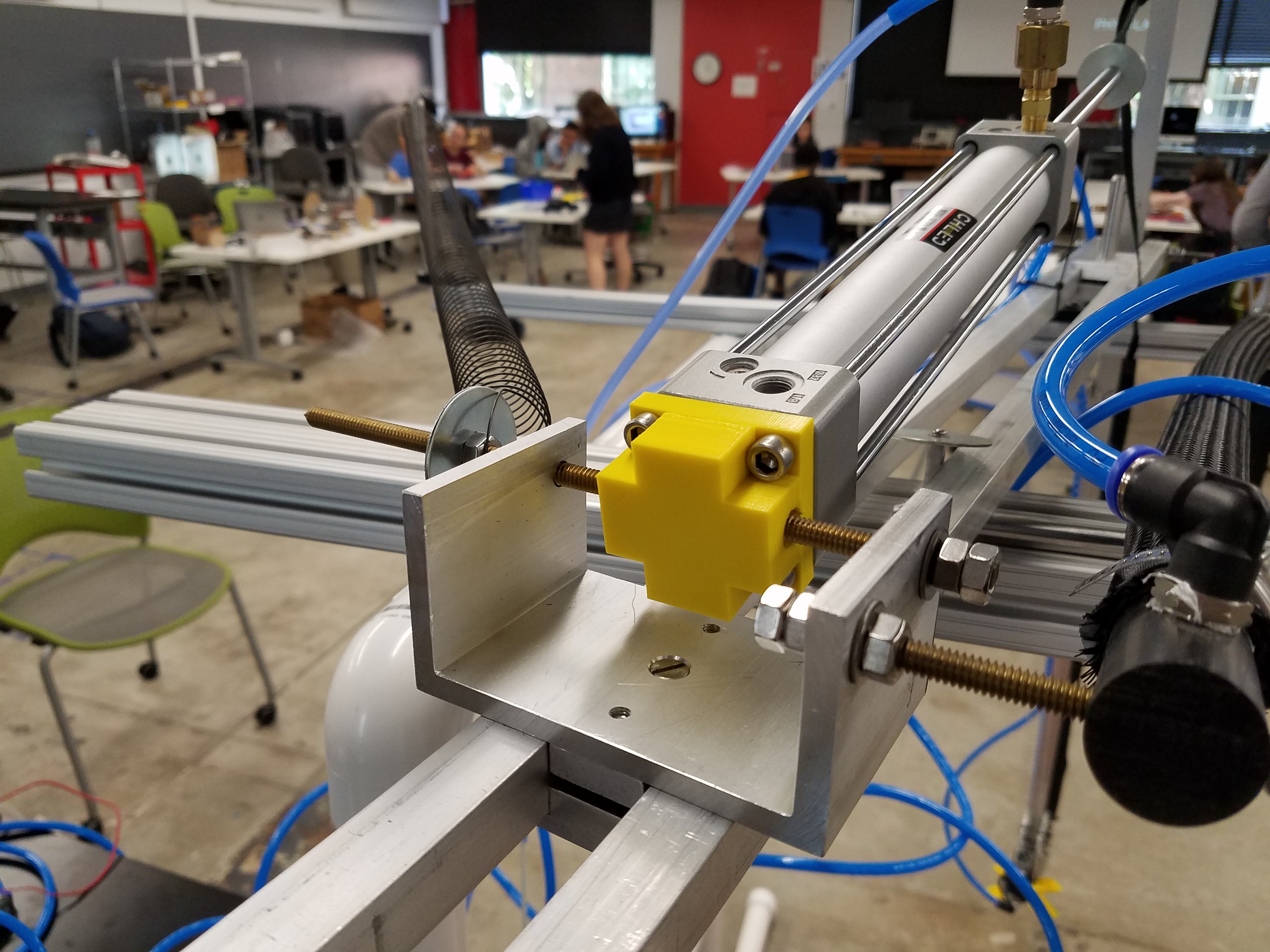
The air cylinder is connected to the shoulder of the robot by a simple shoelace. Ideally, I would want a something more rigid such as a metal rod, but for now this will do.
Here is a quick test I did of several of the robot’s joints, including the wrist:
Circuit Design and Controls
As mentioned earlier, the robot’s movement is powered by an air tank.
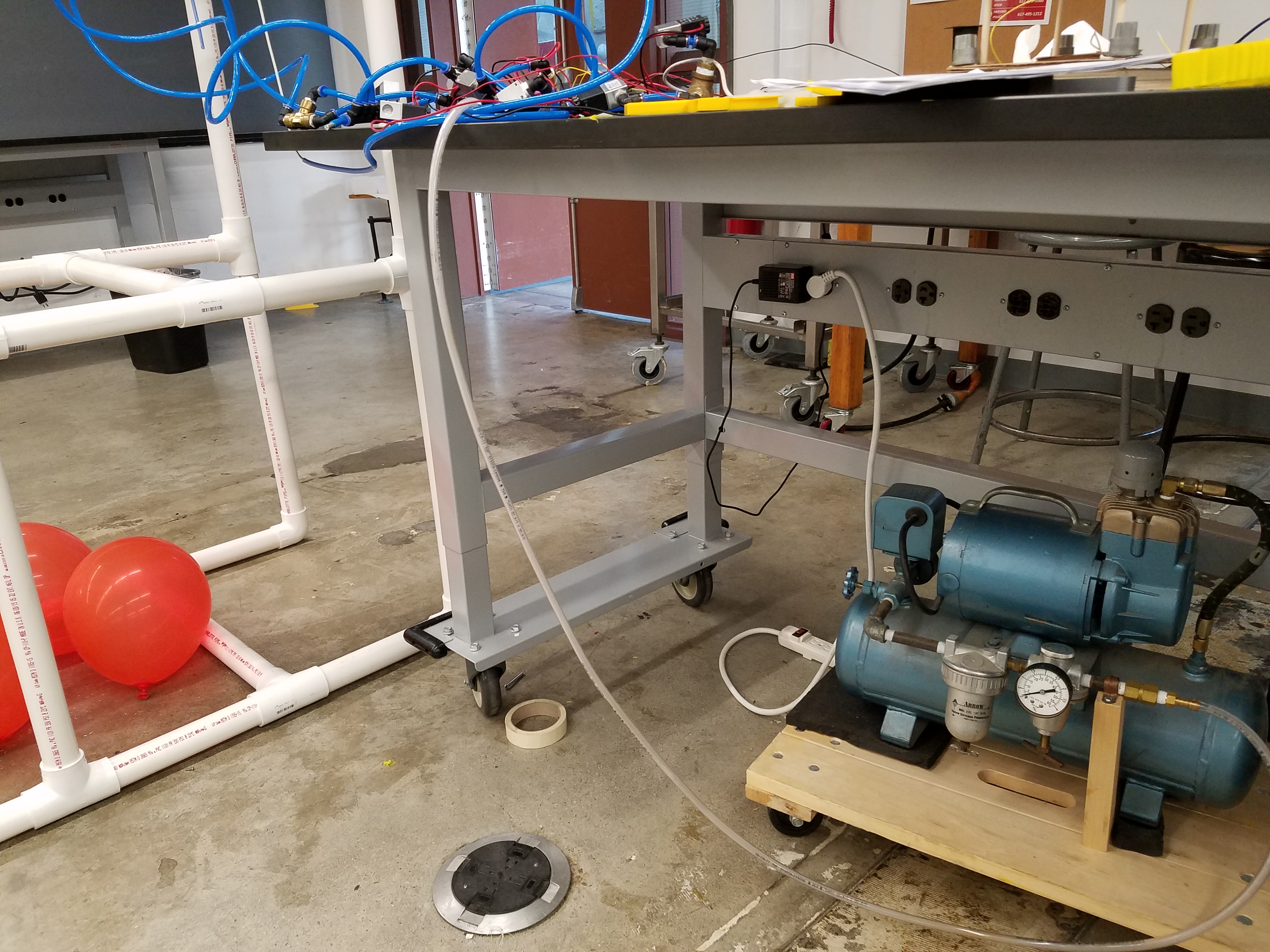
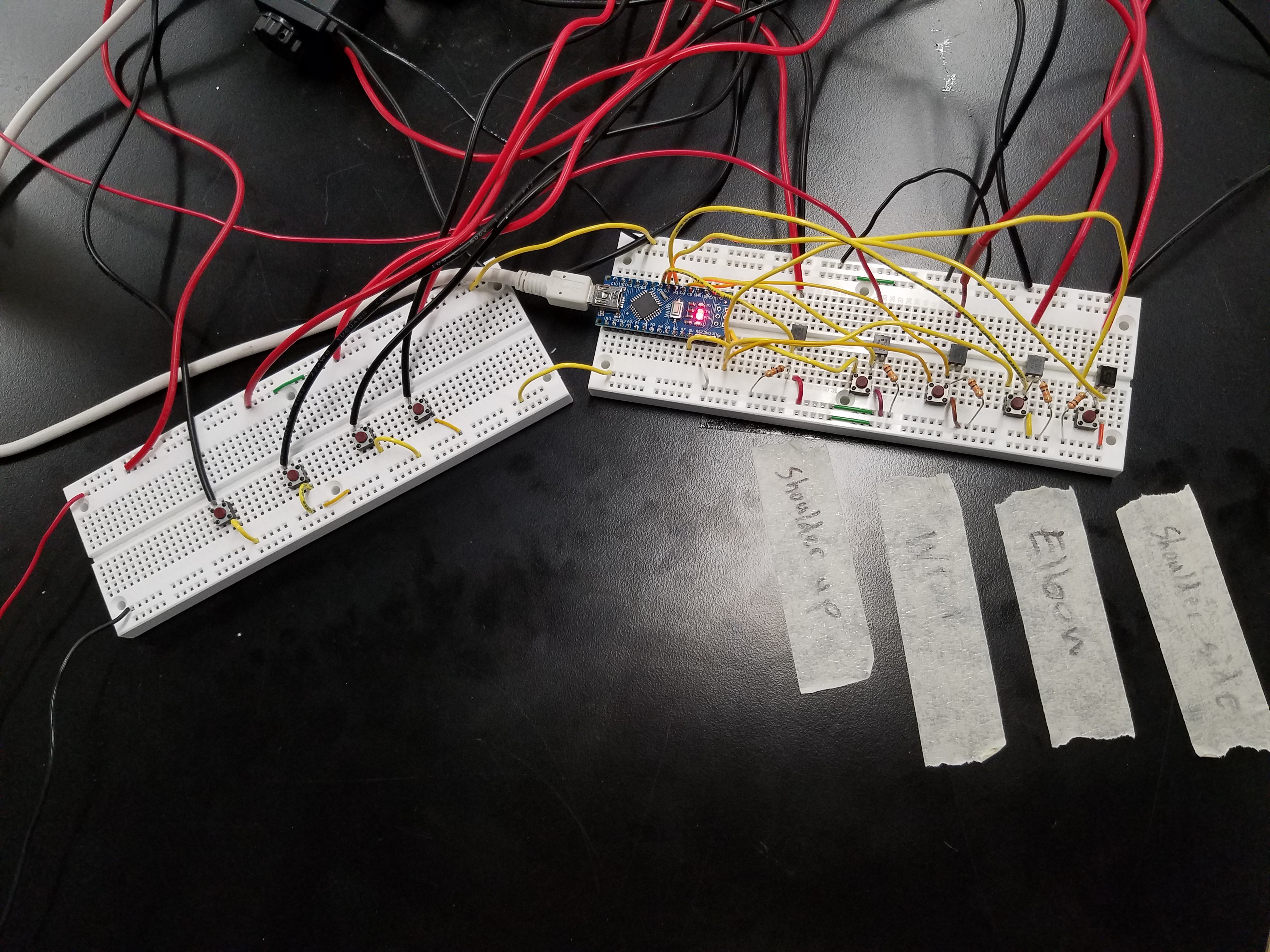
Flow from the air tank into each joint is controlled by air valves, which are in turn controlled by an Arduino Nano and some pushbuttons.
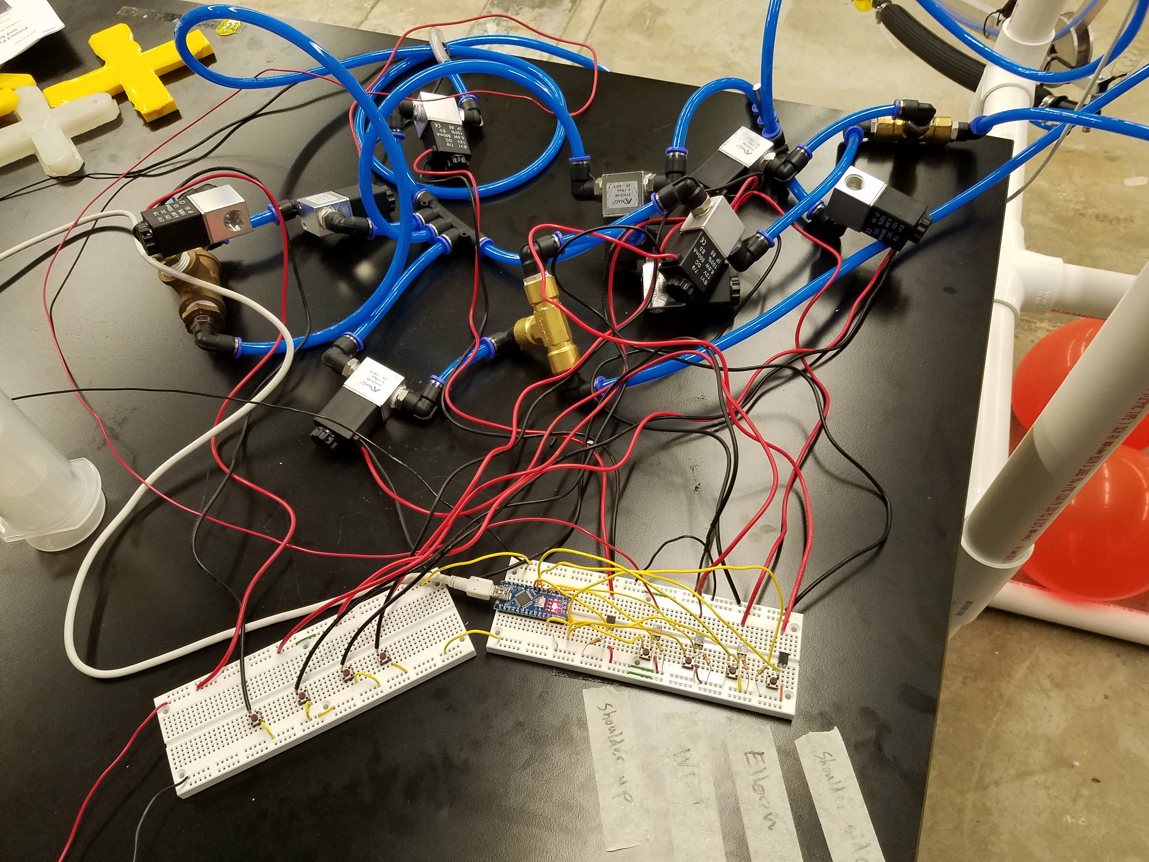
The buttons on the right pump air into the actuators, while the ones on the left are pressure release valves:
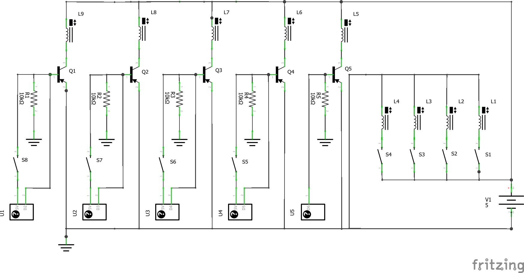
The schematic for the circuit I used is as follows:
Future Improvements
-
The molds for the soft gripper need a serious redesign. The top part of the gripper and the air canals should be two separate molds that can be fit on top of each other, as this would allow a cured top half mold to be simply fit onto the bottom half mold while its silicone is still curing, eliminating the need to remove the cured top half and glue it to the bottom half. Also, the top half of the mold should incorporate the circular solid disk that the soft robotics toolkit website recommends gluing to the very top of the gripper to prevent the center from bulging.
-
Make a PCB, and create an enclosure for this PCB that can be fitted on the robot itself.
-
Create a handheld remote control device to control the joints of the robot
-
Improve the elbow
-
Create a sturdier track that the back end of the robot can slide around easily on
-
Replace the shoelace with something rigid
-
Control the soft gripper with a solenoid-powered syringe or something of that nature